Vehicle Stability Control System Vsc Buzzer Circuit
Brake. Land Cruiser. Urj200, 202 Grj200 Vdj200
DESCRIPTION
WIRING DIAGRAM
INSPECTION PROCEDURE
CHECK CAN COMMUNICATION LINE
CHECK DTC (CAN COMMUNICATION SYSTEM)
PERFORM ACTIVE TEST USING GTS (BUZZER)
INSPECT COMBINATION METER ASSEMBLY
VEHICLE STABILITY CONTROL SYSTEM - VSC Buzzer Circuit |
DESCRIPTION
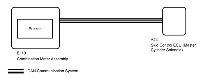
The skid control ECU (master cylinder solenoid) is connected to the combination meter assembly via CAN communication.The combination meter assembly has a built-in buzzer.
WIRING DIAGRAM
INSPECTION PROCEDURE
- NOTICE:
- After replacing the master cylinder solenoid, perform zero point calibration and store the system information (Click here).
| 1.CHECK CAN COMMUNICATION LINE |
Turn the ignition switch off.
Connect the GTS to the DLC3.
Turn the ignition switch to ON and the GTS on.
Select "CAN Bus Check" from the System Selection Menu screen, and follow the prompts on the screen to inspect the CAN Bus.
- OK:
- "CAN Bus Check" indicates no malfunctions in CAN communication.
ResultResult
| Proceed to
|
OK
| A
|
NG (for LHD (with Central Gateway ECU))
| B
|
NG (for LHD (without Central Gateway ECU))
| C
|
NG (for RHD (with Central Gateway ECU))
| D
|
NG (for RHD (without Central Gateway ECU))
| E
|
| | GO TO CAN COMMUNICATION SYSTEM (HOW TO PROCEED WITH TROUBLESHOOTING) (Click here) |
|
|
| | GO TO CAN COMMUNICATION SYSTEM (HOW TO PROCEED WITH TROUBLESHOOTING) (Click here) |
|
|
| | GO TO CAN COMMUNICATION SYSTEM (HOW TO PROCEED WITH TROUBLESHOOTING) (Click here) |
|
|
| | GO TO CAN COMMUNICATION SYSTEM (HOW TO PROCEED WITH TROUBLESHOOTING) (Click here) |
|
|
| 2.CHECK DTC (CAN COMMUNICATION SYSTEM) |
Turn the ignition switch off.
Connect the GTS to the DLC3.
Turn the ignition switch to ON and the GTS on.
for LHD (with Central Gateway ECU):
Check for DTCs (Click here).
for LHD (without Central Gateway ECU):
Check for DTCs (Click here).
for RHD (with Central Gateway ECU):
Check for DTCs (Click here).
for RHD (without Central Gateway ECU):
Check for DTCs (Click here).
ResultResult
| Proceed to
|
CAN DTC is not output
| A
|
CAN DTC is output (for LHD (with Central Gateway ECU))
| B
|
CAN DTC is output (for LHD (without Central Gateway ECU))
| C
|
CAN DTC is output (for RHD (with Central Gateway ECU))
| D
|
CAN DTC is output (for RHD (without Central Gateway ECU))
| E
|
| | GO TO CAN COMMUNICATION SYSTEM (HOW TO PROCEED WITH TROUBLESHOOTING) (Click here) |
|
|
| | GO TO CAN COMMUNICATION SYSTEM (HOW TO PROCEED WITH TROUBLESHOOTING) (Click here) |
|
|
| | GO TO CAN COMMUNICATION SYSTEM (HOW TO PROCEED WITH TROUBLESHOOTING) (Click here) |
|
|
| | GO TO CAN COMMUNICATION SYSTEM (HOW TO PROCEED WITH TROUBLESHOOTING) (Click here) |
|
|
| 3.PERFORM ACTIVE TEST USING GTS (BUZZER) |
Turn the ignition switch off.
Connect the GTS to the DLC3.
Turn the ignition switch to ON.
Turn the GTS on.
Enter the following menus: Chassis / ABS/VSC/TRC / Active Test.
ABS/VSC/TRCTester Display
| Test Part
| Control Range
| Diagnostic Note
|
Buzzer
| Buzzer
| Buzzer ON/OFF
| The buzzer can be heard.
|
When performing the Buzzer Active Test, check Buzzer in the Data List (Click here).
ABS/VSC/TRCTester Display
| Measurement Item/Range
| Normal Condition
| Diagnostic Note
|
Buzzer
| Buzzer/ ON or OFF
| ON: Buzzer on
OFF: Buzzer off
| The combination meter assembly has a built-in buzzer.
|
ResultResult
| Proceed to
|
Data List Display
| Data List Display when Performing Active Test ON/OFF Operation
|
ON
| Changes between ON and OFF
| A
|
Does not change between ON and OFF
| B
|
OFF
| Changes between ON and OFF
| A
|
Does not change between ON and OFF
| B
|
| A |
|
|
|
| GO TO METER / GAUGE SYSTEM (HOW TO PROCEED WITH TROUBLESHOOTING) (Click here) |
|
| 4.INSPECT COMBINATION METER ASSEMBLY |
Inspect the combination meter assembly (Click here).
ResultResult
| Proceed to
|
NG
| A
|
OK (for LHD)
| B
|
OK (for RHD)
| C
|