Dtc P0340 Camshaft Position Sensor Circuit Malfunction
DESCRIPTION
MONITOR DESCRIPTION
WIRING DIAGRAM
INSPECTION PROCEDURE
CHECK HARNESS AND CONNECTOR (SENSOR POWER SOURCE)
CHECK HARNESS AND CONNECTOR (VVT SENSOR FOR INTAKE SIDE - ECM)
CHECK SENSOR INSTALLATION
CHECK INTAKE CAMSHAFT (TEETH)
REPLACE VVT SENSOR (for Intake Side)
CHECK WHETHER DTC OUTPUT RECURS
DTC P0340 Camshaft Position Sensor Circuit Malfunction |
DTC P0342 Camshaft Position Sensor "A" Circuit Low Input (Bank 1 or Single Sensor) |
DTC P0343 Camshaft Position Sensor "A" Circuit High Input (Bank 1 or Single Sensor) |
DTC P0345 Camshaft Position Sensor "A" Circuit (Bank 2) |
DTC P0347 Camshaft Position Sensor "A" Circuit Low Input (Bank 2) |
DTC P0348 Camshaft Position Sensor "A" Circuit High Input (Bank 2) |
DESCRIPTION
The intake camshaft Variable Valve Timing (VVT) sensor (VV1, 2 signal) consists of a magnet and MRE (Magnetic Resistance Element).The intake camshaft has 3 teeth on its outer circumference. When the intake camshaft rotates, changes occur in the air gaps between the teeth and MRE, which affects the magnetic field. As a result, the resistance of the MRE material fluctuates. The VVT sensor converts the intake camshaft rotation data into pulse signals, uses the pulse signals to determine the camshaft angle, and sends it to the ECM.The crankshaft position sensor plate has 34 teeth. The crankshaft position sensor generates 34 signals for each revolution. Based on a combination of the VVT signal and NE signal, the ECM detects the crankshaft angle. Then the ECM uses this data to control fuel injection time and injection timing. Also, based on the NE signal, the ECM detects the engine speed.DTC Code
| DTC Detection Condition
| Trouble Area
|
P0340
P0345
| When either condition below is met:
- The input voltage to the ECM remains at below 0.3 V or higher than 4.7 V for 4 seconds when 2 or more seconds have elapsed after turning the engine switch on (IG) (1 trip detection logic).
- No VVT sensor (for intake side of Bank 1, 2) signal is sent to the ECM during cranking (2 trip detection logic).
| - Open or short in VVT sensor (for intake side) circuit
- VVT sensor (for intake side)
- Intake camshaft (for Bank 1, 2)
- Jumped tooth of timing chain
- ECM
|
P0342
P0347
| The output voltage of the VVT sensor (for intake side of Bank 1, 2) is below 0.3 V for 4 seconds (1 trip detection logic).
| - Open or short in VVT sensor (for intake side) circuit
- VVT sensor (for intake side)
- Intake camshaft (for Bank 1, 2)
- Jumped tooth of timing chain
- ECM
|
P0343
P0348
| The output voltage of the VVT sensor (for intake side of Bank 1, 2) is higher than 4.7 V for 4 seconds (1 trip detection logic).
| - Open or short in VVT sensor (for intake side) circuit
- VVT sensor (for intake side)
- Intake camshaft (for Bank 1, 2)
- Jumped tooth of timing chain
- ECM
|
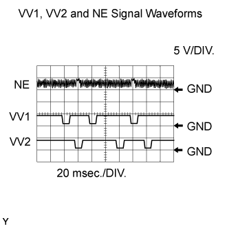
- Reference: Inspection using an oscilloscope
- Standard:
Tester Connection
| Tool Setting
| Condition
| Specified Condition
|
C45-110 (NE+) - C45-111 (NE-)
| 5 V/DIV.
20 msec./DIV.
| Cranking or idling
| The correct waveform is as shown
|
C45-92 (VV1+) - C45-91 (VV1-)
| 5 V/DIV.
20 msec./DIV.
| Cranking or idling
| The correct waveform is as shown
|
C45-87 (VV2+) - C45-88 (VV2-)
| 5 V/DIV.
20 msec./DIV.
| Cranking or idling
| The correct waveform is as shown
|
- HINT:
- VV1+ and VV2+ stand for the VVT sensor (for intake side) signal, and NE+ stands for the CKP sensor signal.
MONITOR DESCRIPTION
If no signal is transmitted by the VVT sensor despite the engine revolving, or the rotations of the camshaft and the crankshaft are not synchronized, the ECM interprets this as a malfunction of the sensor.
WIRING DIAGRAM
INSPECTION PROCEDURE
- HINT:
- Read freeze frame data using the intelligent tester. Freeze frame data records the engine condition when malfunctions are detected. When troubleshooting, freeze frame data can help determine if the vehicle was moving or stationary, if the engine was warmed up or not, if the air-fuel ratio was lean or rich, and other data from the time the malfunction occurred.
- Bank 1 refers to the bank that includes the No. 1 cylinder*.
*: The No. 1 cylinder is the cylinder which is farthest from the transmission.
- Bank 2 refers to the bank that does not include the No. 1 cylinder.
| 1.CHECK HARNESS AND CONNECTOR (SENSOR POWER SOURCE) |
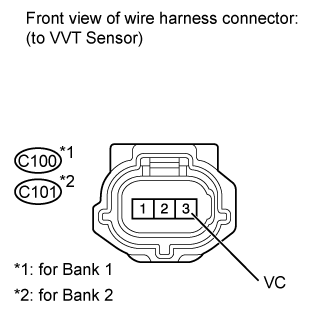
Disconnect the C100 or C101 VVT sensor connector.
Measure the voltage according to the value(s) in the table below.
- Standard Voltage:
Tester Connection
| Condition
| Specified Condition
|
C100-3 (VC) - Body ground
| Engine switch on (IG)
| 4.5 to 5.0 V
|
C101-3 (VC) - Body ground
| Engine switch on (IG)
| 4.5 to 5.0 V
|
| | REPAIR OR REPLACE HARNESS OR CONNECTOR |
|
|
| 2.CHECK HARNESS AND CONNECTOR (VVT SENSOR FOR INTAKE SIDE - ECM) |
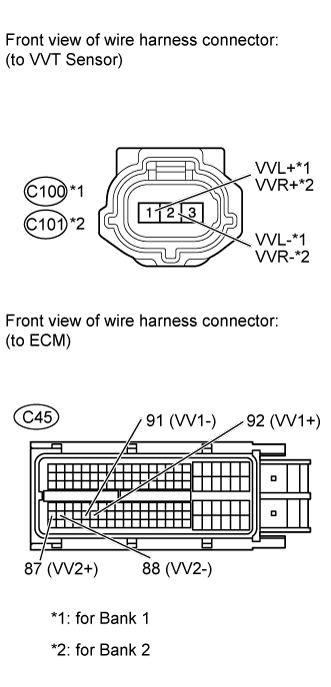
Disconnect the C100 or C101 VVT sensor connector.
Disconnect the C45 ECM connector.
Measure the resistance according to the value(s) in the table below.
- Standard Resistance:
Tester Connection
| Condition
| Specified Condition
|
C100-1 (VVL+) - C45-92 (VV1+)
| Always
| Below 1 Ω
|
C100-2 (VVL-) - C45-91 (VV1-)
| Always
| Below 1 Ω
|
C101-1 (VVR+) - C45-87 (VV2+)
| Always
| Below 1 Ω
|
C101-2 (VVR-) - C45-88 (VV2-)
| Always
| Below 1 Ω
|
C100-1 (VVL+) or C45-92 (VV1+) - Body ground
| Always
| 10 kΩ or higher
|
C100-2 (VVL-) or C45-91 (VV1-) - Body ground
| Always
| 10 kΩ or higher
|
C101-1 (VVR+) or C45-87 (VV2+) - Body ground
| Always
| 10 kΩ or higher
|
C101-2 (VVR-) or C45-88 (VV2-) - Body ground
| Always
| 10 kΩ or higher
|
| | REPAIR OR REPLACE HARNESS OR CONNECTOR |
|
|
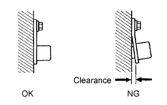
| 3.CHECK SENSOR INSTALLATION |
Check the VVT sensor (for intake side) installation.
- OK:
- Sensor is installed correctly.
| 4.CHECK INTAKE CAMSHAFT (TEETH) |
Check the teeth of the camshaft.
- OK:
- Teeth do not have any cracks or deformation.
| 5.REPLACE VVT SENSOR (for Intake Side) |
Replace the VVT sensor (for Intake Side) (Click here).
| 6.CHECK WHETHER DTC OUTPUT RECURS |
Connect the intelligent tester to the DLC3.
Turn the engine switch on (IG).
Turn the tester on.
Clear DTCs.
Start the engine.
Enter the following menus: Powertrain / Engine and ECT / DTC.
Read DTCs.
ResultResult
| Proceed to
|
No output
| A
|
P0340, P0342, P0343, P0345, P0347 or P0348
| B
|
- HINT:
- If the engine does not start, replace the ECM.