Dtc P2716 Pressure Control Solenoid D Electrical
Drivetrain. Land Cruiser. Urj200, 202 Grj200 Vdj200
DESCRIPTION
MONITOR DESCRIPTION
WIRING DIAGRAM
INSPECTION PROCEDURE
CHECK HARNESS AND CONNECTOR (SHIFT SOLENOID VALVE SLT - TCM)
CHECK HARNESS AND CONNECTOR (TRANSMISSION WIRE - TCM)
INSPECT SHIFT SOLENOID VALVE SLT
DTC P2716 Pressure Control Solenoid "D" Electrical |
DESCRIPTION
Refer to DTC P2714 (Click here).DTC No.
| DTC Detection Condition
- Diagnosis Condition
- Malfunction Status
- Malfunction Time
- Other
| Trouble Area
|
P2716
| - Engine is running
- Shift solenoid valve SLT circuit is open or shorted
- 2 seconds
- 1-trip detection logic
| - Shift solenoid valve SLT
- Transmission wire
- Harness or connector
- TCM
|
MONITOR DESCRIPTION
When an open or short in the shift solenoid valve SLT circuit is detected, the TCM determines that there is a malfunction. The TCM will illuminate the MIL and store this DTC.
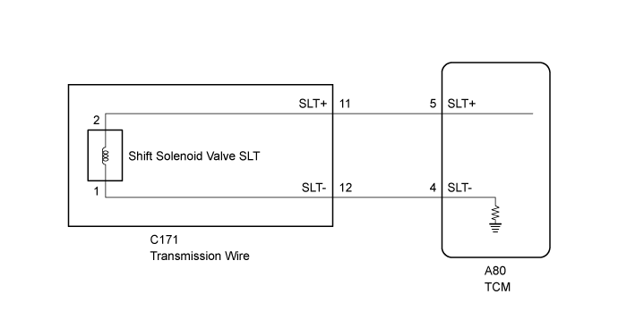
WIRING DIAGRAM
INSPECTION PROCEDURE
- NOTICE:
- Perform registration and/or initialization when parts related to the automatic transmission are replaced (Click here).
- HINT:
- After performing repair, clear the DTCs and perform the following procedure to check that DTCs are not output.
- Perform the D Position Shift Test in Road Test (Click here).
- Check for DTCs again (Click here).
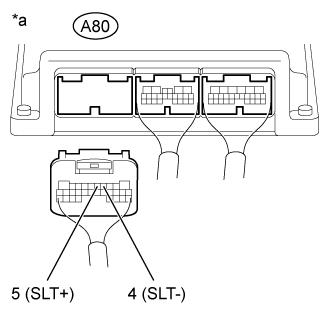
| 1.CHECK HARNESS AND CONNECTOR (SHIFT SOLENOID VALVE SLT - TCM) |
Disconnect the TCM connector.
Measure the resistance according to the value(s) in the table below.
- Standard Resistance:
Tester Connection
| Condition
| Specified Condition
|
A80-5 (SLT+) - A80-4 (SLT-)
| 20°C (68°F)
| 5.0 to 5.6 Ω
|
A80-5 (SLT+) or A80-4 (SLT-) - Body ground
| Always
| 10 kΩ or higher
|
Text in Illustration*a
| Rear view of wire harness connector
(to TCM)
|
| 2.CHECK HARNESS AND CONNECTOR (TRANSMISSION WIRE - TCM) |
Disconnect the C171 transmission wire connector.
Disconnect the A80 TCM connector.
Measure the resistance according to the value(s) in the table below.
- Standard Resistance:
Tester Connection
| Condition
| Specified Condition
|
C171-11 (SLT+) - A80-5 (SLT+)
| Always
| Below 1 Ω
|
C171-12 (SLT-) - A80-4 (SLT-)
| Always
| Below 1 Ω
|
C171-11 (SLT+) or A80-5 (SLT+) - Body ground
| Always
| 10 kΩ or higher
|
C171-12 (SLT-) or A80-4 (SLT-) - Body ground
| Always
| 10 kΩ or higher
|
| | REPAIR OR REPLACE HARNESS OR CONNECTOR |
|
|
| 3.INSPECT SHIFT SOLENOID VALVE SLT |
Remove the shift solenoid valve SLT (Click here).
Measure the resistance according to the value(s) in the table below.
- Standard Resistance:
Tester Connection
| Condition
| Specified Condition
|
Terminal 1 of the shift solenoid valve SLT - Terminal 2
| 20°C (68°F)
| 5.0 to 5.6 Ω
|
Apply 12 V battery voltage to the shift solenoid valve and check that the valve moves and makes an operating noise.
- OK:
Measurement Condition
| Specified Condition
|
- Battery positive (+) with a 21 W bulb → Terminal 2
- Battery negative (-) → Terminal 1
| Valve moves and makes an operating noise
|
Text in Illustration*1
| Shift Solenoid Valve SLT
|