Dtc P2716 Pressure Control Solenoid D Electrical (Shift Solenoid Valve Slt)
Drivetrain. Land Cruiser. Urj200, 202 Grj200 Vdj200
DESCRIPTION
MONITOR DESCRIPTION
WIRING DIAGRAM
INSPECTION PROCEDURE
INSPECT NO. 1 TRANSMISSION WIRE (SHIFT SOLENOID VALVE SLT)
CHECK HARNESS AND CONNECTOR (NO. 1 TRANSMISSION WIRE - ECM)
INSPECT SHIFT SOLENOID VALVE SLT
DTC P2716 Pressure Control Solenoid "D" Electrical (Shift Solenoid Valve SLT) |
DESCRIPTION
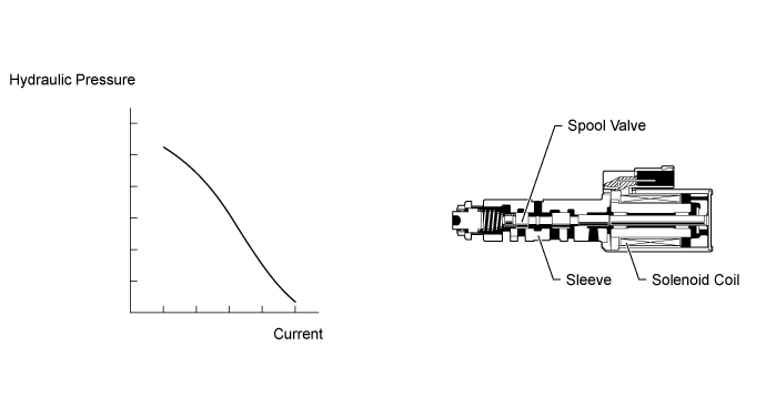
Shift solenoid valve SLT controls the transmission line pressure for smooth transmission operation based on signals from the throttle position sensor and vehicle speed sensor. The ECM adjusts the current to shift solenoid valve SLT to control the hydraulic line pressure coming from the primary regulator valve.Appropriate line pressure assures smooth shifting with varying engine outputs.DTC Code
| DTC Detection Condition
| Trouble Area
|
P2716
| Open or short is detected in shift solenoid valve SLT circuit for 1 second or more while driving (1 trip detection logic)
| - Open or short in shift solenoid valve SLT circuit
- Shift solenoid valve SLT
- ECM
|
MONITOR DESCRIPTION
When an open or short in the shift solenoid valve SLT circuit is detected, the ECM interprets this as a fault. The ECM will turn on the MIL and store the DTC.
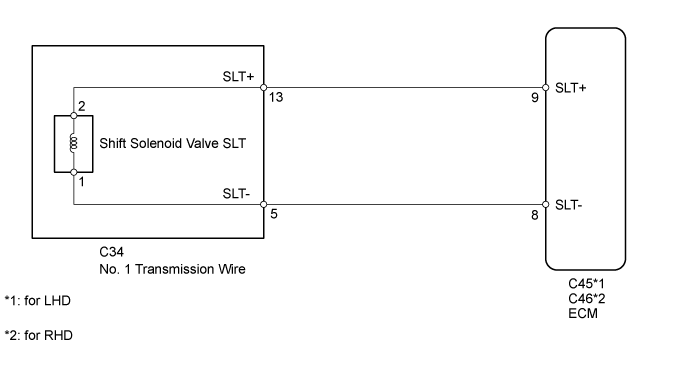
WIRING DIAGRAM
INSPECTION PROCEDURE
| 1.INSPECT NO. 1 TRANSMISSION WIRE (SHIFT SOLENOID VALVE SLT) |
Disconnect the No. 1 transmission wire connector.
Measure the resistance according to the value(s) in the table below.
- Standard Resistance:
Tester Connection
| Condition
| Specified Condition
|
13 (SLT+) - 5 (SLT-)
| 20°C (68°F)
| 5.0 to 5.6 Ω
|
13 (SLT+) - Body ground
| Always
| 10 kΩ or higher
|
5 (SLT-) - Body ground
| Always
| 10 kΩ or higher
|
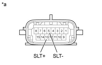
Text in Illustration*a
| Component without harness connected
(No. 1 Transmission Wire)
|
| 2.CHECK HARNESS AND CONNECTOR (NO. 1 TRANSMISSION WIRE - ECM) |
Disconnect the ECM connector.
Measure the resistance according to the value(s) in the table below.
- Standard Resistance:
for LHDTester Connection
| Condition
| Specified Condition
|
C45-9 (SLT+) - C45-8 (SLT-)
| 20°C (68°F)
| 5.0 to 5.6 Ω
|
C45-9 (SLT+) - Body ground
| Always
| 10 kΩ or higher
|
C45-8 (SLT-) - Body ground
| Always
| 10 kΩ or higher
|
for RHDTester Connection
| Condition
| Specified Condition
|
C46-9 (SLT+) - C46-8 (SLT-)
| 20°C (68°F)
| 5.0 to 5.6 Ω
|
C46-9 (SLT+) - Body ground
| Always
| 10 kΩ or higher
|
C46-8 (SLT-) - Body ground
| Always
| 10 kΩ or higher
|
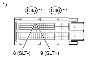
Text in Illustration*1
| for LHD
|
*2
| for RHD
|
*a
| Front view of wire harness connector
(to ECM)
|
| | REPAIR OR REPLACE HARNESS OR CONNECTOR |
|
|
| 3.INSPECT SHIFT SOLENOID VALVE SLT |
Remove shift solenoid valve SLT.
Measure the resistance according to the value(s) in the table below.
- Standard Resistance:
Tester Connection
| Condition
| Specified Condition
|
1 - 2
| 20°C (68°F)
| 5.0 to 5.6 Ω
|
Apply 12 V battery voltage to the shift solenoid valve and check that the valve moves and makes an operating noise.
- OK:
Measurement Condition
| Specified Condition
|
- Battery positive (+) with a 21 W bulb → Terminal 2
- Battery negative (-) → Terminal 1
| Valve moves and makes an operating noise
|
Text in Illustration*a
| Component without harness connected
(Shift Solenoid Valve SLT)
|
| OK |
|
|
|
| REPAIR OR REPLACE NO. 1 TRANSMISSION WIRE (Click here) |
|