Dtc P2759 Torque Converter Clutch Pressure Control Solenoid Control Circuit Electrical
Drivetrain. Land Cruiser. Urj200, 202 Grj200 Vdj200
DESCRIPTION
MONITOR DESCRIPTION
WIRING DIAGRAM
INSPECTION PROCEDURE
CHECK HARNESS AND CONNECTOR (SHIFT SOLENOID VALVE SLU - TCM)
CHECK HARNESS AND CONNECTOR (TRANSMISSION WIRE - TCM)
INSPECT SHIFT SOLENOID VALVE SLU
DTC P2759 Torque Converter Clutch Pressure Control Solenoid Control Circuit Electrical |
DESCRIPTION
The TCM controls the lock-up solenoid using a predetermined current, and performs lock-up and flex lock-up control.DTC No.
| DTC Detection Condition
- Diagnosis Condition
- Malfunction Status
- Malfunction Time
- Other
| Trouble Area
|
P2759
| - Vehicle is being driven
- Shift solenoid valve SLU circuit is open or shorted
- 2 seconds
- 1-trip detection logic
| - Shift solenoid valve SLU
- Transmission wire
- Harness or connector
- TCM
|
MONITOR DESCRIPTION
When an open or short in a shift solenoid valve SLU circuit is detected, the TCM determines that there is a malfunction. The TCM will illuminate the MIL and store this DTC.
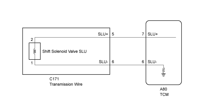
WIRING DIAGRAM
INSPECTION PROCEDURE
- NOTICE:
- Perform registration and/or initialization when parts related to the automatic transmission are replaced (Click here).
- HINT:
- After performing repair, clear the DTCs and perform the following procedure to check that DTCs are not output.
- Perform the Lock-up Function in Road Test (Click here).
- Check for DTCs again (Click here).
| 1.CHECK HARNESS AND CONNECTOR (SHIFT SOLENOID VALVE SLU - TCM) |
Disconnect the TCM connector.
Measure the resistance according to the value(s) in the table below.
- Standard Resistance:
Tester Connection
| Condition
| Specified Condition
|
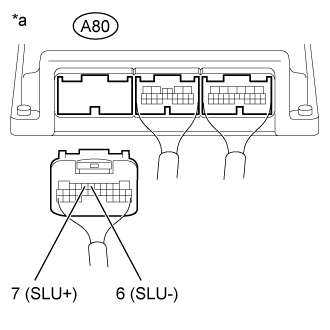
A80-7 (SLU+) - A80-6 (SLU-)
| 20°C (68°F)
| 5.0 to 5.6 Ω
|
A80-7 (SLU+) or A80-6 (SLU-) - Body ground
| Always
| 10 kΩ or higher
|
Text in Illustration*a
| Rear view of wire harness connector
(to TCM)
|
| 2.CHECK HARNESS AND CONNECTOR (TRANSMISSION WIRE - TCM) |
Disconnect the C171 transmission wire connector.
Disconnect the A80 TCM connector.
Measure the resistance according to the value(s) in the table below.
- Standard Resistance:
Tester Connection
| Condition
| Specified Condition
|
C171-5 (SLU+) - A80-7 (SLU+)
| Always
| Below 1 Ω
|
C171-6 (SLU-) - A80-6 (SLU-)
| Always
| Below 1 Ω
|
C171-5 (SLU+) or A80-7 (SLU+) - Body ground
| Always
| 10 kΩ or higher
|
C171-6 (SLU-) or A80-6 (SLU-) - Body ground
| Always
| 10 kΩ or higher
|
| | REPAIR OR REPLACE HARNESS OR CONNECTOR |
|
|
| 3.INSPECT SHIFT SOLENOID VALVE SLU |
Remove the shift solenoid valve SLU (Click here).
Measure the resistance according to the value(s) in the table below.
- Standard Resistance:
Tester Connection
| Condition
| Specified Condition
|
Terminal 1 of the shift solenoid valve SLU - Terminal 2
| 20°C (68°F)
| 5.0 to 5.6 Ω
|
Apply 12 V battery voltage to the shift solenoid valve and check that the valve moves and makes an operating noise.
- OK:
Measurement Condition
| Specified Condition
|
- Battery positive (+) with a 21 W bulb → Terminal 2
- Battery negative (-) → Terminal 1
| Valve moves and makes an operating noise
|
Text in Illustration*1
| Shift Solenoid Valve SLU
|