Dtc P0705 Transmission Range Sensor Circuit Malfunction (Prndl Input)
Drivetrain. Land Cruiser. Urj200, 202 Grj200 Vdj200
DESCRIPTION
MONITOR DESCRIPTION
WIRING DIAGRAM
INSPECTION PROCEDURE
ADJUST PARK/NEUTRAL POSITION SWITCH ASSEMBLY
ADJUST TRANSMISSION FLOOR SHIFT ASSEMBLY
READ VALUE USING GTS (SHIFT SW STATUS)
CHECK PARK/NEUTRAL POSITION SWITCH ASSEMBLY (POWER SOURCE)
INSPECT PARK/NEUTRAL POSITION SWITCH ASSEMBLY
CHECK HARNESS AND CONNECTOR (PARK/NEUTRAL POSITION SWITCH ASSEMBLY - TCM)
DTC P0705 Transmission Range Sensor Circuit Malfunction (PRNDL Input) |
DESCRIPTION
The park/neutral position switch detects the shift lever position and sends signals to the TCM.DTC No.
| DTC Detection Condition
- Diagnosis Condition
- Malfunction Status
- Malfunction Time
- Other
| Trouble Area
|
P0705
| - Battery voltage is 9.5 V or higher.
- No signal of the A, B, C and PA signals.
- 5 seconds or more
- 2-trip detection logic
| - Transmission floor shift assembly (incorrect adjustment)
- Park/neutral position switch assembly (incorrect adjustment)
- Park/neutral position switch assembly
- Open or short in park/neutral position switch assembly circuit
- TCM
|
- Battery voltage is 9.5 V or higher.
- Implausible combination of the A, B, C and PA signals.
- 5 seconds or more
- 2-trip detection logic
|
- Battery voltage is 9.5 V or higher, engine speed is more than 400 rpm and vehicle speed is 30 km/h (18.6 mph) or more.
- Uncertain D position combination of the A, B, C and PA signals.
- 30 seconds or more
- 2-trip detection logic
|
- HINT:
Park/neutral position switch normal operation chart:Shift Lever Position
| A switch
| B switch
| C switch
| PA switch
|
P
| ON
| OFF
| OFF
| ON
|
R
| ON
| ON
| OFF
| OFF
|
N
| OFF
| ON
| OFF
| ON
|
D
| OFF
| ON
| ON
| OFF
|
Park/neutral position switch malfunction operation chart:Malfunction Status
| A switch
| B switch
| C switch
| PA switch
|
No signal
| OFF
| OFF
| OFF
| OFF
|
Implausible combination
| ON
| ON
| OFF
| ON
|
ON
| ON
| ON
| ON
|
ON
| OFF
| ON
| ON
|
ON
| OFF
| ON
| OFF
|
OFF
| OFF
| ON
| ON
|
OFF
| OFF
| OFF
| ON
|
ON
| OFF
| OFF
| OFF
|
OFF
| OFF
| ON
| OFF
|
ON
| ON
| ON
| OFF
|
OFF
| ON
| OFF
| OFF
|
Uncertain D position
| OFF
| ON
| ON
| ON
|
MONITOR DESCRIPTION
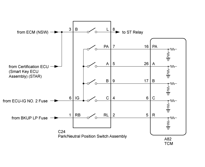
This DTC indicates a problem with the park/neutral position switch assembly or the wire harness in the park/neutral position switch assembly circuit.The park/neutral position switch assembly detects the shift lever position and sends signals to the TCM.For safety, the park/neutral position switch assembly detects the shift lever position so that the engine can be started only when the shift lever is in P or N.The park/neutral position switch assembly sends signals to the TCM according to the shift lever position (P, N, R or D).The TCM determines that there is a problem with the switch or related parts if a malfunction occurs in the park/neutral position switch signal. The TCM will illuminate the MIL and store the DTC.
WIRING DIAGRAM
INSPECTION PROCEDURE
- NOTICE:
- Perform registration and/or initialization when parts related to the automatic transmission are replaced (Click here).
- Inspect the fuses for circuits related to this system before performing the following inspection procedure.
- HINT:
- After the repair, clear the DTCs and perform the following procedure to check that DTCs are not output.
- Turn the engine switch on (IG).*1
- Wait with the shift lever in each position (P, R, N and D) for 5 seconds or more.*2
- Drive the vehicle 30 km/h (19 mph) or more for 30 seconds or more.*3
- Turn the engine switch off.
- Perform steps (*1) through (*3) again.
- Check for DTCs again (Click here).
| 1.ADJUST PARK/NEUTRAL POSITION SWITCH ASSEMBLY |
Adjust the park/neutral position switch assembly (Click here).
| 2.ADJUST TRANSMISSION FLOOR SHIFT ASSEMBLY |
Adjust the transmission floor shift assembly (Click here).
| 3.READ VALUE USING GTS (SHIFT SW STATUS) |
Connect the GTS to the DLC3.
Turn the engine switch on (IG).
Turn the GTS on.
Enter the following menus: Powertrain / ECT / Data List.
According to the display on the GTS, read the Data List.
ECTTester Display
| Measurement Item/Range
| Normal Condition
| Diagnostic Note
|
Shift SW Status (P Range)
| Park/neutral position switch status/
ON or OFF
| - ON: Shift lever is in P
- OFF: Shift lever is not in P
| When shift lever position displayed on the GTS differs from actual position, adjustment of park/neutral position switch assembly or shift cable may be incorrect.
|
Shift SW Status (R Range)
| Park/neutral position switch status/
ON or OFF
| - ON: Shift lever is in R
- OFF: Shift lever is not in R
| When shift lever position displayed on the GTS differs from actual position, adjustment of park/neutral position switch assembly or shift cable may be incorrect.
|
Shift SW Status (N Range)
| Park/neutral position switch status/
ON or OFF
| - ON: Shift lever is in N
- OFF: Shift lever is not in N
| When shift lever position displayed on the GTS differs from actual position, adjustment of park/neutral position switch assembly or shift cable may be incorrect.
|
Shift SW Status (D Range)
| Park/neutral position switch status/
ON or OFF
| - ON: Shift lever is in D or S
- OFF: Shift lever is not in D or S
| When shift lever position displayed on the GTS differs from actual position, adjustment of park/neutral position switch assembly or shift cable may be incorrect.
|
ResultResult
| Proceed to
|
Data List value is not within the normal condition
| A
|
Data List value is within the normal condition
| B
|
| 4.CHECK PARK/NEUTRAL POSITION SWITCH ASSEMBLY (POWER SOURCE) |
Disconnect the park/neutral position switch assembly connector.
Turn the engine switch on (IG).
Measure the voltage according to the value(s) in the table below.
- Standard Voltage:
Tester Connection
| Switch Condition
| Specified Condition
|
C24-6 (IG) - Body ground
| Engine switch on (IG)
| 11 to 14 V
|
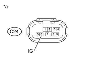
Text in Illustration*a
| Front view of wire harness connector
(to Park/Neutral Position Switch Assembly)
|
| | REPAIR OR REPLACE HARNESS OR CONNECTOR (PARK/NEUTRAL POSITION SWITCH ASSEMBLY - BATTERY) |
|
|
| 5.INSPECT PARK/NEUTRAL POSITION SWITCH ASSEMBLY |
Disconnect the park/neutral position switch assembly connector.
Measure the resistance according to the value(s) in the table below.
- Standard Resistance:
Tester Connection
| Condition
| Specified Condition
|
6 (IG) - 4 (C)
| Shift lever in D and S
| Below 1 Ω
|
6 (IG) - 5 (A)
| Shift lever in P and R
| Below 1 Ω
|
6 (IG) - 7 (PA)
| Shift lever in P and N
| Below 1 Ω
|
6 (IG) - 9 (B)
| Shift lever in R, N, D and S
| Below 1 Ω
|
6 (IG) - 4 (C)
| Shift lever not in D and S
| 10 kΩ or higher
|
6 (IG) - 5 (A)
| Shift lever not in P and R
| 10 kΩ or higher
|
6 (IG) - 7 (PA)
| Shift lever not in P and N
| 10 kΩ or higher
|
6 (IG) - 9 (B)
| Shift lever not in R, N, D and S
| 10 kΩ or higher
|
1 (RB) - 4 (C), 5 (A), 7 (PA) and 9 (B)
| Shift lever in P, R, N, D and S
| 10 kΩ or higher
|
3 (B) - 4 (C), 5 (A), 7 (PA) and 9 (B)
| Shift lever in P, R, N, D and S
| 10 kΩ or higher
|
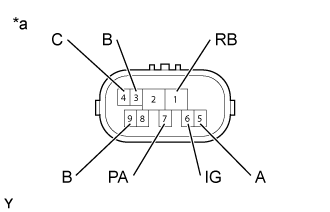
Text in Illustration*a
| Component without harness connected
(Park/Neutral Position Switch Assembly)
|
| | REPLACE PARK/NEUTRAL POSITION SWITCH ASSEMBLY (Click here) |
|
|
| 6.CHECK HARNESS AND CONNECTOR (PARK/NEUTRAL POSITION SWITCH ASSEMBLY - TCM) |
Disconnect the C24 park/neutral position switch assembly connector.
Disconnect the A82 TCM connector.
Measure the resistance according to the value(s) in the table below.
- Standard Resistance:
Tester Connection
| Condition
| Specified Condition
|
C24-4 (C) - A82-6 (C)
| Always
| Below 1 Ω
|
C24-5 (A) - A82-26 (A)
| Always
| Below 1 Ω
|
C24-7 (PA) - A82-16 (PA)
| Always
| Below 1 Ω
|
C24-9 (B) - A82-17 (B)
| Always
| Below 1 Ω
|
C24-4 (C) or A82-6 (C) - Body ground
| Always
| 10 kΩ or higher
|
C24-5 (A) or A82-26 (A) - Body ground
| Always
| 10 kΩ or higher
|
C24-7 (PA) or A82-16 (PA) - Body ground
| Always
| 10 kΩ or higher
|
C24-9 (B) or A82-17 (B) - Body ground
| Always
| 10 kΩ or higher
|
| | REPAIR OR REPLACE HARNESS OR CONNECTOR |
|
|