Theft Deterrent System (W/ Entry And Start System) Certification Ecu Power Source Circuit
DESCRIPTION
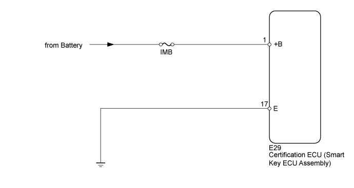
WIRING DIAGRAM
INSPECTION PROCEDURE
INSPECT FUSE (IMB)
CHECK HARNESS AND CONNECTOR (CERTIFICATION ECU [SMART KEY ECU ASSEMBLY] - BATTERY AND BODY GROUND)
THEFT DETERRENT SYSTEM (w/ Entry and Start System) - Certification ECU Power Source Circuit |
DESCRIPTION
This circuit provides power to operate the certification ECU (smart key ECU assembly).
WIRING DIAGRAM
INSPECTION PROCEDURE
Remove the IMB fuse from the engine room relay block.
Measure the resistance according to the value(s) in the table below.
- Standard Resistance:
Tester Connection
| Condition
| Specified Condition
|
IMB fuse
| Always
| Below 1 Ω
|
| 2.CHECK HARNESS AND CONNECTOR (CERTIFICATION ECU [SMART KEY ECU ASSEMBLY] - BATTERY AND BODY GROUND) |
Disconnect the E29 ECU connector.
Measure the resistance according to the value(s) in the table below.
- Standard Resistance:
Tester Connection
| Condition
| Specified Condition
|
E29-17 (E) - Body ground
| Always
| Below 1 Ω
|
Measure the voltage according to the value(s) in the table below.
- Standard Voltage:
Tester Connection
| Condition
| Specified Condition
|
E29-1 (+B) - Body ground
| Always
| 11 to 14 V
|
| | REPAIR OR REPLACE HARNESS OR CONNECTOR |
|
|
| OK |
|
|
|
| PROCEED TO NEXT CIRCUIT INSPECTION SHOWN IN PROBLEM SYMPTOMS TABLE (Click here) |
|