Dtc P0617 Starter Relay Circuit High
DESCRIPTION
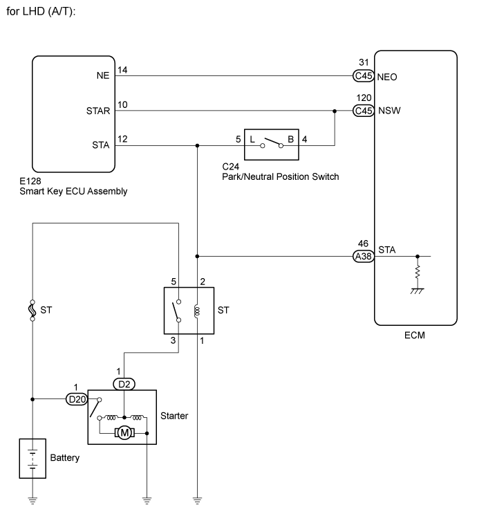
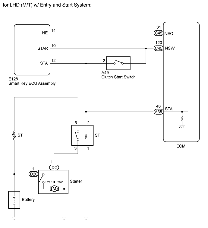
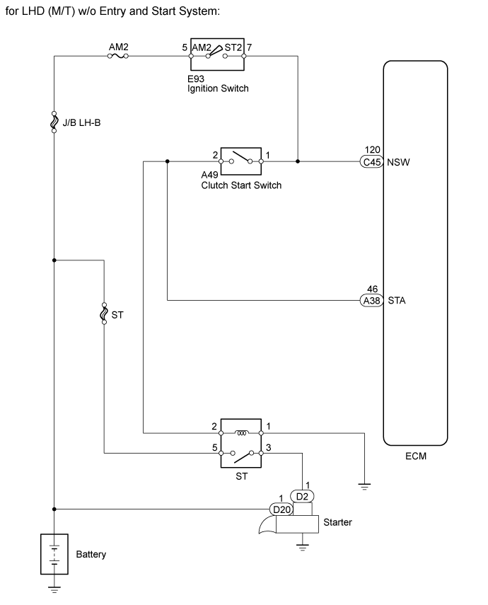
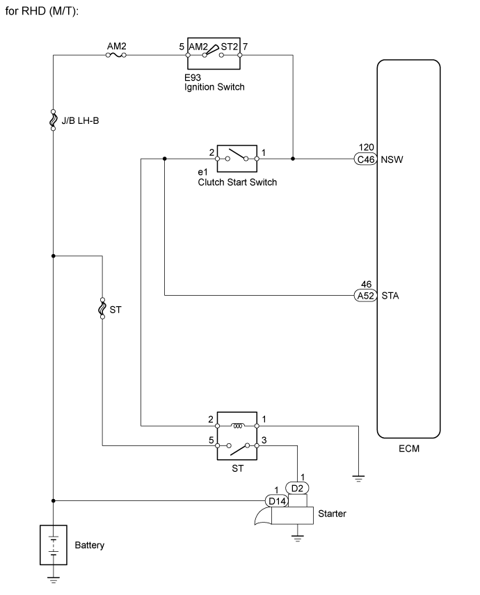
WIRING DIAGRAM
INSPECTION PROCEDURE
READ VALUE USING GTS (STARTER SIGNAL)
INSPECT PARK/NEUTRAL POSITION SWITCH ASSEMBLY
REPAIR OR REPLACE HARNESS OR CONNECTOR (PARK/NEUTRAL POSITION SWITCH ASSEMBLY - ECM)
CHECK WHETHER DTC OUTPUT RECURS
INSPECT CLUTCH START SWITCH ASSEMBLY
REPAIR OR REPLACE HARNESS OR CONNECTOR (CLUTCH START SWITCH ASSEMBLY - ECM)
CHECK WHETHER DTC OUTPUT RECURS
DTC P0617 Starter Relay Circuit High |
DESCRIPTION
While the engine is being cranked, the positive battery voltage is applied to terminal STA of the ECM. If the ECM detects the Starter Control (STA) signal while the vehicle is being driven, it determines that there is a malfunction in the STA circuit. The ECM then illuminates the MIL and stores the DTC.This monitor runs when the vehicle is driven at 20 km/h (12.4 mph) for over 20 seconds.DTC No.
| DTC Detection Condition
| Trouble Area
|
P0617
| When conditions (a), (b) and (c) are met, a positive (+B) battery voltage of 10.5 V or higher is applied to the ECM for 20 seconds (1 trip detection logic):
- (a) The vehicle speed is 20 km/h (12.4 mph) or more.
- (b) The engine speed is 1000 rpm or more.
- (c) The STA signal is ON.
| - Park/Neutral Position (PNP) switch
- Clutch start switch
- ST relay circuit
- ECM
|
WIRING DIAGRAM
INSPECTION PROCEDURE
- HINT:
- The following troubleshooting flowchart is based on the premise that the engine can be cranked normally.
If the engine does not crank, proceed to Problem Symptoms Table (Click here).
- Read freeze frame data using the GTS. Freeze frame data records the engine condition when malfunctions are detected. When troubleshooting, freeze frame data can help determine if the vehicle was moving or stationary, if the engine was warmed up or not, if the air-fuel ratio was lean or rich, and other data from the time the malfunction occurred.
| 1.READ VALUE USING GTS (STARTER SIGNAL) |
Connect the GTS to the DLC3.
Turn the ignition switch to ON and turn the GTS on.
Enter the following menus: Powertrain / Engine and ECT / Data List / All Data / Starter Signal.
Check the value displayed on the GTS when the ignition switch is turned to the ON and START positions.
- Standard:
Ignition Switch Position
| Starter Signal
|
ON
| OFF
|
START
| ON
|
ResultResult
| Proceed to
|
OK
| A
|
NG (for Automatic transmission)
| B
|
NG (for Manual transmission)
| C
|
| 2.INSPECT PARK/NEUTRAL POSITION SWITCH ASSEMBLY |
Inspect the park/neutral position switch assembly (Click here).
| | REPLACE PARK/NEUTRAL POSITION SWITCH ASSEMBLY (Click here) |
|
|
| 3.REPAIR OR REPLACE HARNESS OR CONNECTOR (PARK/NEUTRAL POSITION SWITCH ASSEMBLY - ECM) |
| 4.CHECK WHETHER DTC OUTPUT RECURS |
Connect the GTS to the DLC3.
Turn the ignition switch to ON.
Turn the GTS on.
Clear the DTCs (Click here).
Drive the vehicle at a vehicle speed of more than 24 km/h (15 mph) for more than 20 seconds.
Enter the following menus: Powertrain / Engine and ECT / Trouble Codes.
Read the DTCs.
ResultResult
| Proceed to
|
P0617 is output
| A
|
No DTC is output
| B
|
| 5.INSPECT CLUTCH START SWITCH ASSEMBLY |
Inspect the clutch start switch assembly (for LHD) (Click here).
Inspect the clutch start switch assembly (for RHD) (Click here).
ResultResult
| Proceed to
|
OK
| A
|
NG (for LHD)
| B
|
NG (for RHD)
| C
|
| 6.REPAIR OR REPLACE HARNESS OR CONNECTOR (CLUTCH START SWITCH ASSEMBLY - ECM) |
| 7.CHECK WHETHER DTC OUTPUT RECURS |
Connect the GTS to the DLC3.
Turn the ignition switch to ON.
Turn the GTS on.
Clear the DTCs (Click here).
Drive the vehicle at a vehicle speed of more than 24 km/h (15 mph) for more than 20 seconds.
Enter the following menus: Powertrain / Engine and ECT / Trouble Codes.
Read the DTCs.
ResultResult
| Proceed to
|
P0617 is output
| A
|
No DTC is output
| B
|