Front Power Seat Control System (W/ Seat Position Memory System) -- Terminals Of Ecu |
| CHECK FRONT POWER SEAT SWITCH LH (for LHD) |

Disconnect the c39 and c40 switch connectors.
Measure the voltage and resistance according to the value(s) in the table below.
Terminal No. (Symbol) Wiring Color Terminal Description Condition Specified Condition c39-1 (GND) - Body ground W-B - Body ground Ground Always Below 1 Ω c39-6 (+B) - c39-1 (GND) L - W-B Power source Always 11 to 14 V c40-12 (SYSB) - c39-1 (GND) R - W-B System power source Always 11 to 14 V Reconnect the c39 and c40 switch connectors.
Measure the voltage according to the value(s) in the table below.
Terminal No. (Symbol) Wiring Color Terminal Description Condition Specified Condition c39-2 (SLD+) - c39-1 (GND) B - W-B Sliding motor signal (forward) Slide switch off Below 1 V Slide switch front on 11 to 14 V c39-4 (SLD-) - c39-1 (GND) P - W-B Sliding motor signal (rearward) Slide switch off Below 1 V Slide switch rear on 11 to 14 V c39-7 (FRV+) - c39-1 (GND) R - W-B Front vertical motor signal (upward) Front vertical switch off Below 1 V Front vertical switch up on 11 to 14 V c39-5 (FRV-) - c39-1 (GND) LG - W-B Front vertical motor signal (downward) Front vertical switch off Below 1 V Front vertical switch down on 11 to 14 V c39-8 (LFT+) - c39-1 (GND) G - W-B Lifter motor signal (upward) Lifter switch off Below 1 V Lifter switch up on 11 to 14 V c39-11 (LFT-) - c39-1 (GND) W - W-B Lifter motor signal (downward) Lifter switch off Below 1 V Lifter switch down on 11 to 14 V c39-9 (RCL+) - c39-1 (GND) GR - W-B Reclining motor signal (forward) Reclining switch off Below 1 V Reclining switch front on 11 to 14 V c39-12 (RCL-) - c39-1 (GND) P - W-B Reclining motor signal (rearward) Reclining switch off Below 1 V Reclining switch rear on 11 to 14 V
| CHECK FRONT POWER SEAT SWITCH RH (for RHD) |

Disconnect the c46 and c47 switch connectors.
Measure the voltage and resistance according to the value(s) in the table below.
Terminal No. (Symbol) Wiring Color Terminal Description Condition Specified Condition c46-1 (GND) - Body ground W-B - Body ground Ground Always Below 1 Ω c46-6 (+B2) - c46-1 (GND) L - W-B Power source Always 11 to 14 V c47-12 (SYSB) - c46-1 (GND) R - W-B System power source Always 11 to 14 V Reconnect the c46 and c47 switch connectors.
Measure the voltage according to the value(s) in the table below.
Terminal No. (Symbol) Wiring Color Terminal Description Condition Specified Condition c46-2 (SLDF) - c46-1 (GND) B - W-B Sliding motor signal (forward) Slide switch off Below 1 V Slide switch front on 11 to 14 V c46-4 (SLDR) - c46-1 (GND) P - W-B Sliding motor signal (rearward) Slide switch off Below 1 V Slide switch rear on 11 to 14 V c46-7 (FUP) - c46-1 (GND) R - W-B Front vertical motor signal (upward) Front vertical switch off Below 1 V Front vertical switch up on 11 to 14 V c46-5 (FDWN) - c46-1 (GND) LG - W-B Front vertical motor signal (downward) Front vertical switch off Below 1 V Front vertical switch down on 11 to 14 V c46-8 (LUP) - c46-1 (GND) G - W-B Lifter motor signal (upward) Lifter switch off Below 1 V Lifter switch up on 11 to 14 V c46-11 (LDWN) - c46-1 (GND) W - W-B Lifter motor signal (downward) Lifter switch off Below 1 V Lifter switch down on 11 to 14 V c46-9 (RCLF) - c46-1 (GND) GR - W-B Reclining motor signal (forward) Reclining switch off Below 1 V Reclining switch front on 11 to 14 V c46-12 (RCLR) - c46-1 (GND) P - W-B Reclining motor signal (rearward) Reclining switch off Below 1 V Reclining switch rear on 11 to 14 V
| CHECK OUTER MIRROR CONTROL ECU ASSEMBLY LH (for LHD) |
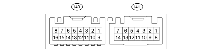
Disconnect the I40 and I41 ECU connectors.
Measure the voltage and resistance according to the value(s) in the table below.
Terminal No. (Symbol) Wiring Color Terminal Description Condition Specified Condition I41-6 (CPUB) - I41-7 (GND) G - W-B Battery power supply Always 11 to 14 V I41-14 (BDR) - I41-7 (GND) L - W-B Battery power supply Always 11 to 14 V I41-5 (SIG) - I41-7 (GND) B - W-B Ignition power supply Engine switch on (IG) 11 to 14 V I41-5 (SIG) - I41-7 (GND) B - W-B Ignition power supply Always Below 1 V I41-7 (GND) - Body ground W-B - Body ground Ground Always Below 1 Ω Reconnect the I40 and I41 ECU connectors.
Measure the voltage according to the value(s) in the table below.
Terminal No. (Symbol) Wiring Color Terminal Description Condition Specified Condition I41-2 (M1) - I41-7 (GND) G - W-B M1 switch signal for seat memory switch LH M1 switch on Below 1 V M1 switch off 11 to 14 V I41-3 (M2) - I41-7 (GND) W - W-B M2 switch signal for seat memory switch LH M2 switch on Below 1 V M2 switch off 11 to 14 V I41-4 (M3) - I41-7 (GND) R - W-B M3 switch signal for seat memory switch LH M3 switch on Below 1 V M3 switch off 11 to 14 V I41-1 (MM) - I41-7 (GND) B - W-B SET switch signal for seat memory switch LH SET switch on Below 1 V SET switch off 11 to 14 V
| CHECK OUTER MIRROR CONTROL ECU ASSEMBLY RH (for RHD) |
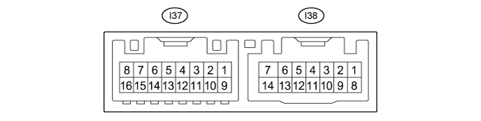
Disconnect the I37 and I38 ECU connectors.
Measure the voltage and resistance according to the value(s) in the table below.
Terminal No. (Symbol) Wiring Color Terminal Description Condition Specified Condition I38-6 (CPUB) - I38-7 (GND) G - W-B Battery power supply Always 11 to 14 V I38-14 (BDR) - I38-7 (GND) L - W-B Battery power supply Always 11 to 14 V I38-5 (SIG) - I38-7 (GND) B - W-B Ignition power supply Engine switch on (IG) 11 to 14 V I38-5 (SIG) - I38-7 (GND) B - W-B Ignition power supply Always Below 1 V I38-7 (GND) - Body ground W-B - Body ground Ground Always Below 1 Ω Reconnect the I37 and I38 ECU connectors.
Measure the voltage according to the value(s) in the table below.
Terminal No. (Symbol) Wiring Color Terminal Description Condition Specified Condition I38-2 (M1) - I38-7 (GND) G - W-B M1 switch signal for seat memory switch RH M1 switch on Below 1 V M1 switch off 11 to 14 V I38-3 (M2) - I38-7 (GND) W - W-B M2 switch signal for seat memory switch RH M2 switch on Below 1 V M2 switch off 11 to 14 V I38-4 (M3) - I38-7 (GND) R - W-B M3 switch signal for seat memory switch RH M3 switch on Below 1 V M3 switch off 11 to 14 V I38-1 (MM) - I38-7 (GND) B - W-B SET switch signal for seat memory switch RH SET switch on Below 1 V SET switch off 11 to 14 V