Engine Hybrid System. Land Cruiser. Urj200, 202 Grj200 Vdj200
Cruise Control. Land Cruiser. Urj200, 202 Grj200 Vdj200
Dynamic Radar Cruise Control System -- Terminals Of Ecu |
| CHECK ECM (for 1UR-FE) |
- HINT:
- As the ECM connector is a waterproof connector, it is not possible to check the voltage of each terminal or check the waveform with an oscilloscope while the ECM is installed in the vehicle.
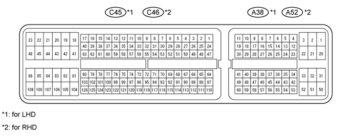
Disconnect the A38*1 and C45*1 or A52*2 and C46*2 ECM connectors.
- *1: for LHD
- *2: for RHD
- *1: for LHD
Measure the voltage and resistance according to the value(s) in the table below.
Terminal No. (Symbol) Wiring Color Terminal Description Condition Specified Condition A38*1-16 (TC) - Body ground
A52*2-16 (TC) - Body groundV-W - Body ground Terminal TC of DLC3 Engine switch on (IG) 11 to 14 V Engine switch off Below 1 V C45*1-81 (E1) - Body ground
C46*2-81 (E1) - Body groundBR - Body ground ECM ground Always Below 1 Ω C45*1-27 (D) - Body ground
C46*2-27 (D) - Body groundG - Body ground Park/neutral position switch signal Engine switch on (IG)
Shift lever in D11 to 14 V Engine switch on (IG)
Shift lever not in DBelow 1 V A38*1-38 (SFTU) - Body ground
A52*2-38 (SFTU) - Body groundY - Body ground Park/neutral position switch signal Engine switch on (IG)
Shift lever in SBelow 1 Ω Engine switch on (IG)
Shift lever in +10 kΩ or higher A38*1-25 (S) - Body ground
A52*2-25 (S) - Body groundW - Body ground Park/neutral position switch signal Engine switch on (IG)
Shift lever in S11 to 14 V Engine switch on (IG)
Shift lever not in SBelow 1 V A38*1-27 (SFTD) - Body ground
A52*2-27 (SFTD) - Body groundL - Body ground Park/neutral position switch signal Engine switch on (IG)
Shift lever in S10 kΩ or higher Engine switch on (IG)
Shift lever in -Below 1 Ω A38*1-36 (STP) - Body ground
A52*2-36 (STP) - Body groundR - Body ground Stop light signal Engine switch on (IG)
Brake pedal depressed11 to 14 V Engine switch on (IG)
Brake pedal releasedBelow 1 V A38*1-35 (ST1-) - Body ground
A52*2-35 (ST1-) - Body groundR-W - Body ground Stop light signal (opposite to STP terminal) Engine switch on (IG)
Brake pedal depressedBelow 1 V Engine switch on (IG)
Brake pedal released11 to 14 V A38*1-45 (CCS) - Body ground
A52*2-45 (CCS) - Body groundL - Body ground Cruise control main switch signal Engine switch on (IG)
Main switch off1 MΩ or higher Engine switch on (IG)
CANCEL switch held on1510 to 1570 Ω Engine switch on (IG)
-SET switch held on620 to 640 Ω Engine switch on (IG)
+RES switch held on235 to 245 Ω Engine switch on (IG)
Main switch onBelow 2.5 Ω A38*1-37 (CCHG) - Body ground
A52*2-37 (CCHG) - Body groundP-B - Body ground Distance control switch signal Engine switch on (IG)
Main switch on
MODE switch held onBelow 1 V Engine switch on (IG)
Main switch on
MODE switch off11 to 14 V - *1: for LHD
- *2: for RHD
- *1: for LHD
| CHECK ECM (for 3UR-FE) |

- HINT:
- As the ECM connector is a waterproof connector, it is not possible to check the voltage of each terminal or check the waveform with an oscilloscope while the ECM is installed in the vehicle.
Disconnect the A38 and C45 ECM connectors.
Measure the voltage and resistance according to the value(s) in the table below.
If the result is not as specified, there may be a malfunction on the wire harness side.Terminal No. (Symbol) Wiring Color Terminal Description Condition Specified Condition A38-16 (TC) - Body ground V-W - Body ground Terminal TC of DLC3 Engine switch on (IG) 11 to 14 V Engine switch off Below 1 V C45-81 (E1) - Body ground W-B - Body ground ECM ground Always Below 1 Ω C45-27 (D) - Body ground G - Body ground Park/neutral position switch signal Engine switch on (IG)
Shift lever in D11 to 14 V Engine switch on (IG)
Shift lever not in DBelow 1 V A38-38 (SFTU) - Body ground Y - Body ground Park/neutral position switch signal Engine switch on (IG)
Shift lever in SBelow 1 Ω Engine switch on (IG)
Shift lever in +10 kΩ or higher A38-25 (S) - Body ground W - Body ground Park/neutral position switch signal Engine switch on (IG)
Shift lever in S11 to 14 V Engine switch on (IG)
Shift lever not in SBelow 1 V A38-27 (SFTD) - Body ground L - Body ground Park/neutral position switch signal Engine switch on (IG)
Shift lever in S10 kΩ or higher Engine switch on (IG)
Shift lever in -Below 1 Ω A38-36 (STP) - Body ground R - Body ground Stop light signal Engine switch on (IG)
Brake pedal depressed11 to 14 V Engine switch on (IG)
Brake pedal releasedBelow 1 V A38-35 (ST1-) - Body ground R-W - Body ground Stop light signal (opposite to STP terminal) Engine switch on (IG)
Brake pedal depressedBelow 1 V Engine switch on (IG)
Brake pedal released11 to 14 V A38-45 (CCS) - Body ground L - Body ground Cruise control main switch signal Engine switch on (IG)
Main switch off1 MΩ or higher Engine switch on (IG)
CANCEL switch held on1510 to 1570 Ω Engine switch on (IG)
-SET switch held on620 to 640 Ω Engine switch on (IG)
+RES switch held on235 to 245 Ω Engine switch on (IG)
Main switch onBelow 2.5 Ω A38-37 (CCHG) - Body ground P-B - Body ground Distance control switch signal Engine switch on (IG)
Main switch on
MODE switch held onBelow 1 V Engine switch on (IG)
Main switch on
MODE switch off11 to 14 V
| CHECK DISTANCE CONTROL ECU |

Disconnect the E108 distance control ECU connector.
Measure the voltage and resistance according to the value(s) in the table below.
If the result is not as specified, there may be a malfunction on the wire harness side.Terminal No. (Symbol) Wiring Color Terminal Description Condition Specified Condition E108-1 (B) - Body ground R - Body ground Distance control ECU power source line Engine switch on (IG) 11 to 14 V E108-3 (WASH) - Body ground L - Body ground Windshield wiper switch signal Engine switch on (IG)
Windshield wiper switch on11 to 14 V Engine switch on (IG)
Windshield wiper switch offBelow 1 V E108-12 (GND) - Body ground BR - Body ground Ground Always Below 1 Ω E108-13 (IGB) - Body ground R - Body ground Engine switch on (IG) signal Engine switch on (IG) 11 to 14 V Engine switch off Below 1 V E108-16 (MODE) - Body ground W - Body ground Distance control switch signal Engine switch on (IG)
Distance control switch onBelow 1 V Engine switch on (IG)
Distance control switch off11 to 14 V E108-22 (LRDD) - E108-10 (SGND) B - R Millimeter wave radar sensor input signal Engine switch on (IG) Pulse generation
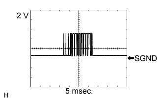
(See waveform 1)E108-23 (LRRD) - E108-10 (SGND) W - R Millimeter wave radar sensor output signal Engine switch on (IG) Pulse generation
(See waveform 2)Using an oscilloscope, check waveform 1.
Item Content Terminal No. (Symbol) E108-22 (LRDD) - E108-10 (SGND) Tool Setting 2 V/DIV., 10 msec./DIV. Condition Engine switch on (IG) Using an oscilloscope, check waveform 2.
Item Content Terminal No. (Symbol) E108-23 (LRRD) - E108-10 (SGND) Tool Setting 2 V/DIV., 5 msec./DIV. Condition Engine switch on (IG)
 |
 |
| CHECK MILLIMETER WAVE RADAR SENSOR |

Disconnect the A56 millimeter wave radar sensor connector.
Measure the voltage according to the value(s) in the table below.
If the result is not as specified, there may be a malfunction on the wire harness side.Terminal No. (Symbol) Wiring Color Terminal Description Condition Specified Condition A56-3 (LRDD) - A56-2 (SGND) B - R Millimeter wave radar sensor output signal Engine switch on (IG) Pulse generation
(See waveform 3)A56-4 (LRRD) - A56-2 (SGND) W - R Millimeter wave radar sensor input signal Engine switch on (IG) Pulse generation
(See waveform 4)A56-5 (IGB) - A56-2 (SGND) R - R Engine switch on (IG) signal Engine switch on (IG) 11 to 14 V Engine switch off Below 1 V Using an oscilloscope, check waveform 3.
Item Content Terminal No. (Symbol) A56-3 (LRDD) - A56-2 (SGND) Tool Setting 2 V/DIV., 10 msec./DIV. Condition Engine switch on (IG) Using an oscilloscope, check waveform 4.
Item Content Terminal No. (Symbol) A56-4 (LRRD) - A56-2 (SGND) Tool Setting 2 V/DIV., 5 msec./DIV. Condition Engine switch on (IG)
|
|