Engine Hybrid System. Land Cruiser. Urj200, 202 Grj200 Vdj200
1Gr-Fe Engine Control. Land Cruiser. Urj200, 202 Grj200 Vdj200
Sfi System -- Freeze Frame Data |
| DESCRIPTION |
- The ECM records vehicle and driving condition information (fuel system information, calculated load, engine coolant temperature, fuel trim, engine speed, vehicle speed, etc.) as freeze frame data the moment a DTC is stored. When troubleshooting, freeze frame data can be helpful in determining whether the vehicle was moving or stationary, whether the engine was warmed up or not, whether the air-fuel ratio was lean or rich, as well as other data recorded at the time of a malfunction.
- HINT:
- If it is impossible to duplicate the problem even though a DTC is output, check the freeze frame data.
The ECM records engine conditions in the form of freeze frame data every 0.5 seconds. Using the GTS, 5 separate sets of freeze frame data can be checked.
- 3 data sets from before the DTC was stored.
- 1 data set from when the DTC was stored.
- 1 data set from after the DTC was stored.
- These data sets can be used to simulate the condition of the vehicle from around the time of the occurrence of the malfunction. The data may assist in identifying the cause of the malfunction, and in judging whether it was temporary or not.
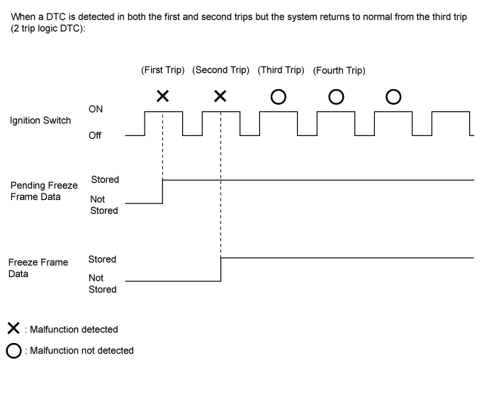
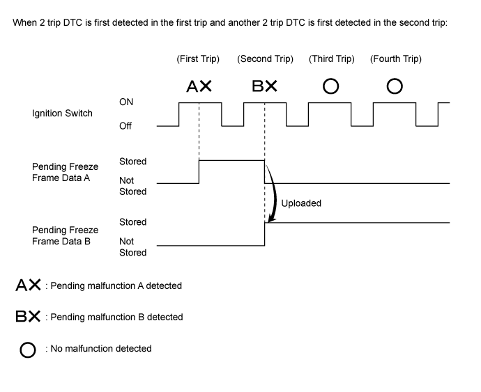
| PENDING FREEZE FRAME DATA |
- HINT:
- Pending freeze frame data is stored when a 2 trip DTC is first detected during the first trip.
Connect the GTS to the DLC3.
Turn the ignition switch to ON.
Turn the GTS on.
Enter the following menus: Powertrain / Engine and ECT / Trouble Codes.
Select a DTC in order to display its pending freeze frame data.
- HINT:
- Pending freeze frame data is cleared when any of the following occurs.
- Using the GTS, the DTCs cleared.
- The cable is disconnected from the negative (-) battery terminal.
- 40 trips with the engine fully warmed up have been performed after returning to normal. (Pending freeze frame data will not be cleared by only returning the system to normal.)
- With previous pending freeze frame data stored, if pending freeze frame data is newly stored when a 2 trip DTC is detected in the first trip, the old freeze frame data will be replaced with the new one of the newly detected DTC in the next trip.
| LIST OF FREEZE FRAME DATA |
| Tester Display | Measurement Item | Diagnostic Note |
| Vehicle Speed | Vehicle speed | Speed indicated on the speedometer. |
| Engine Speed | Engine speed | - |
| Calculate Load | Calculated load | Load calculated by the ECM. |
| Vehicle Load | Vehicle load | - |
| MAF | Mass airflow volume | If the value is approximately 0.0 gm/s:
|
| Atmosphere Pressure | Atmospheric pressure | - |
| Coolant Temp | Engine coolant temperature | If the value is -40°C (-40°F), the sensor circuit is open. If the value is 140°C (284°F) or higher, the sensor circuit is shorted. |
| Intake Air | Intake air temperature | If the value is -40°C (-40°F), the sensor circuit is open. If the value is 140°C (284°F) or higher, the sensor circuit is shorted. |
| Engine Run Time | Accumulated engine running time | - |
| Initial Engine Coolant Temp | Engine coolant temperature at engine start | - |
| Initial Intake Air Temp | Intake air temperature at engine start | - |
| Battery Voltage | Battery voltage | - |
| Glow Indicator Supported | Status of glow indicator supported | - |
| Glow Indicator | Glow indicator | - |
| Accel Sens. No.1 Volt % | Absolute Accelerator Pedal Position (APP) No. 1 | - |
| Accel Sens. No.2 Volt % | Absolute APP No. 2 | - |
| Throttle Sensor Volt % | Throttle sensor position | - |
| Throttl Sensor #2 Volt % | Throttle sensor position #2 | - |
| Throttle Sensor Position | Throttle position | - |
| Throttle Motor DUTY | Throttle actuator | - |
| Throttle Position | Throttle position | For use when engine stall, starting problems or rough idle is present. |
| ISC Flow | Flow rate calculated using information from each sensor | For use when engine stall, starting problems or rough idle is present. |
| ISC Position | Requested opening amount calculated using ISC control | For use when engine stall, starting problems or rough idle is present. |
| ISC Feedback Value | ISC feedback compensation amount | For use when engine stall, starting problems or rough idle is present. |
| ISC Learning Value | ISC learned compensation amount | For use when engine stall, starting problems or rough idle is present. |
| Electric Load Feedback Val | Compensation flow rate according to electrical load | For use when engine stall, starting problems or rough idle is present. |
| Air Conditioner FB Val | Compensation flow rate according to air conditioner load | For use when engine stall, starting problems or rough idle is present. |
| PS Feedback Val | Compensation flow rate according to power steering load | For use when engine stall, starting problems or rough idle is present. |
| Low Revolution Control | Low engine speed control operation state | For use when engine stall, starting problems or rough idle is present. |
| N Range Status | Shift lever N status | For use when engine stall, starting problems or rough idle is present. |
| Eng Stall Control FB Flow | Intake air compensation flow rate | For use when engine stall, starting problems or rough idle is present. |
| Deposit Loss Flow | Flow loss due to deposits | For use when engine stall, starting problems or rough idle is present. |
| Fuel Pump Duty | Fuel pump duty | - |
| Injector (Port) | Injection period of No. 1 cylinder | - |
| Injection Volum (Cylinder 1) | Injection volume | - |
| Current Fuel Type | Current fuel type | Used to identify the current fuel type: Gasoline |
| EVAP (Purge) VSV | EVAP purge VSV duty ratio | - |
| Evap Purge Flow | Ratio of evaporative purge flow to intake air volume | - |
| Purge Density Learn Value | Purge density learned value | - |
| EVAP Purge VSV | EVAP purge VSV | - |
| Purge Cut VSV Duty | Purge cut VSV duty | - |
| Target Air-Fuel Ratio | Ratio compared to stoichiometric level | - |
| AF Lambda B1S1 | Fuel trim at air fuel ratio sensor | - |
| AF Lambda B2S1 | Fuel trim at air fuel ratio sensor | - |
| AFS Voltage B1S1 AFS Voltage B2S1 | Air fuel ratio sensor voltage | Performing Control the Injection Volume or Control the Injection Volume for A/F Sensor function of the Active Test enables the technician to check the output voltage of the sensor. |
| AFS Current B1S1 | Air fuel ratio sensor current | - |
| AFS Current B2S1 | Air fuel ratio sensor current | - |
| A/F Heater Duty B1S1 | Air fuel ratio sensor heater duty ratio (for Bank 1) | - |
| A/F Heater Duty B2S1 | Air fuel ratio sensor heater duty ratio (for Bank 2) | - |
| O2S B1S2 O2S B2S2 | Heated oxygen sensor output | Performing Control the Injection Volume or Control the Injection Volume for A/F Sensor function of the Active Test enables the technician to check the output voltage of the sensor. |
| O2 Heater B1S2 O2 Heater B2S2 | Heated oxygen sensor heater (for Sensor 2) | - |
| O2 Heater Curr Val B1S2 O2 Heater Curr Val B2S2 | Heated oxygen sensor current (for Sensor 2) | - |
| Short FT #1 | Short-term fuel trim | Short-term fuel compensation used to maintain the air-fuel ratio at the stoichiometric air-fuel ratio. |
| Long FT #1 | Long-term fuel trim |
|
| A/F Learn Value Idle #1 | Air-fuel ratio learned value for idling (bank 1) | Learning is performed when idling with the engine warmed up (engine coolant temperature is 75°C [167°F] or higher). |
| A/F Learn Value Low #1 | Air-fuel ratio learned value for low engine loads (bank 1) | Learning is performed when driving with the engine warmed up (engine coolant temperature is 75°C [167°F] or higher) and operating in the low load range (when the range of engine loads is divided into four parts). |
| A/F Learn Value Mid1 #1 | Air-fuel ratio learned value for mid-sized engine loads 1 (bank 1) | Learning is performed when driving with the engine warmed up (engine coolant temperature is 75°C [167°F] or higher) and operating in the mid-size load range closer to the low load range (when the range of engine loads is divided into four parts). |
| A/F Learn Value Mid2 #1 | Air-fuel ratio learned value for mid-sized engine loads 2 (bank 1) | Learning is performed when driving with the engine warmed up (engine coolant temperature is 75°C [167°F] or higher) and operating in the mid-size load range closer to the high load range (when the range of engine loads is divided into four parts). |
| A/F Learn Value High #1 | Air-fuel ratio learned value for high engine loads (bank 1) | Learning is performed when driving with the engine warmed up (engine coolant temperature is 75°C [167°F] or higher) and operating in the high load range (when the range of engine loads is divided into four parts). |
| Total FT #1 | Total fuel trim | - |
| Short FT #2 | Short-term fuel trim | Short-term fuel compensation used to maintain the air-fuel ratio at the stoichiometric air-fuel ratio. |
| Long FT #2 | Long-term fuel trim |
|
| A/F Learn Value Idle #2 | Air-fuel ratio learned value for idling (bank 2) | Learning is performed when idling with the engine warmed up (engine coolant temperature is 75°C [167°F] or higher). |
| A/F Learn Value Low #2 | Air-fuel ratio learned value for low engine loads (bank 2) | Learning is performed when driving with the engine warmed up (engine coolant temperature is 75°C [167°F] or higher) and operating in the low load range (when the range of engine loads is divided into four parts). |
| A/F Learn Value Mid1 #2 | Air-fuel ratio learned value for mid-sized engine loads 1 (bank 2) | Learning is performed when driving with the engine warmed up (engine coolant temperature is 75°C [167°F] or higher) and operating in the mid-size load range closer to the low load range (when the range of engine loads is divided into four parts). |
| A/F Learn Value Mid2 #2 | Air-fuel ratio learned value for mid-sized engine loads 2 (bank 2) | Learning is performed when driving with the engine warmed up (engine coolant temperature is 75°C [167°F] or higher) and operating in the mid-size load range closer to the high load range (when the range of engine loads is divided into four parts). |
| A/F Learn Value High #2 | Air-fuel ratio learned value for high engine loads (bank 2) | Learning is performed when driving with the engine warmed up (engine coolant temperature is 75°C [167°F] or higher) and operating in the high load range (when the range of engine loads is divided into four parts). |
| Total FT #2 | Total fuel trim | - |
| Fuel System Status #1 | Fuel system status (for Bank 1) |
|
| Fuel System Status #2 | Fuel system status (for Bank 2) |
|
| Air Pump Pressure (Absolute) | Air pump pressure (for Bank 1) | - |
| Air Pump2 Pressure (Absolute) | Air pump pressure (for Bank 2) | - |
| Air Pump Pulsation Pressure | Air pump pulsation pressure | - |
| Secondary Air Control VSV | Secondary air control VSV status | - |
| 2nd Air System Status | Secondary air injection system status | - |
| AI Test | Secondary air injection system operation prohibition | - |
| Subfreezing Conditions | Subfreezing conditions status | - |
| Air Pump Freeze | Air pump freeze status | - |
| Air Switching Valve Freeze | Switching valve freeze status | - |
| Air Switching Valve2 Freeze | Switching valve 2 freeze status | - |
| Air Pump Heater | Air pump heater status | - |
| IGN Advance | Ignition advance | - |
| Knock Feedback Value | Knocking feedback value | - |
| Knock Correct Learn Value | Knocking correction learned value | - |
| Idle Spark Advn Ctrl #1 | Individual cylinder timing advance compensation amount (No. 1) | For use when engine stall, starting problems or rough idle is present. |
| Idle Spark Advn Ctrl #2 | Individual cylinder timing advance compensation amount (No. 2) | For use when engine stall, starting problems or rough idle is present. |
| Idle Spark Advn Ctrl #3 | Individual cylinder timing advance compensation amount (No. 3) | For use when engine stall, starting problems or rough idle is present. |
| Idle Spark Advn Ctrl #4 | Individual cylinder timing advance compensation amount (No. 4) | For use when engine stall, starting problems or rough idle is present. |
| Idle Spark Advn Ctrl #5 | Individual cylinder timing advance compensation amount (No. 5) | For use when engine stall, starting problems or rough idle is present. |
| Idle Spark Advn Ctrl #6 | Individual cylinder timing advance compensation amount (No. 6) | For use when engine stall, starting problems or rough idle is present. |
| VVT Control Status #1 | VVT control status (for Bank 1) | - |
| VVT Control Status #2 | VVT control status (for Bank 2) | - |
| VVT Advance Fail | VVT control failure status | - |
| Catalyst Temp B1S1 | Estimated catalyst temperature (for Bank 1 Sensor 1) | - |
| Catalyst Temp B2S1 | Estimated catalyst temperature (for Bank 2 Sensor 1) | - |
| Catalyst Temp B1S2 | Estimated catalyst temperature (for Bank 1 Sensor 2) | - |
| Catalyst Temp B2S2 | Estimated catalyst temperature (for Bank 2 Sensor 2) | - |
| Starter Signal | Starter switch signal | - |
| Power Steering Signal | Power steering oil pressure sensor status | - |
| Neutral Position SW Signal | Park/neutral position (PNP) switch signal | - |
| Clutch Switch | Clutch switch status | - |
| Clutch Start SW | Clutch start switch status | - |
| Transfer L4 | L4 status of the transfer | - |
| Stop Light Switch | Stop light switch | - |
| A/C Signal | A/C signal | - |
| Closed Throttle Position SW | Closed throttle position switch | - |
| Fuel Cut Condition | Fuel cut condition | - |
| Immobiliser Communication | Immobiliser communication | - |
| TC Terminal | TC terminal status | - |
| Time after DTC Cleared | Cumulative time after DTCs cleared | - |
| Distance from DTC Cleared | Accumulated distance driven after DTCs cleared | - |
| Warmup Cycle Cleared DTC | Warmup cycles after DTCs cleared | - |
| Dist Batt Cable Disconnect | Total distance vehicle driven after battery cable disconnected | - |
| IG OFF Elapsed Time | Cumulative time after ignition switch off | - |
| TC and TE1 | TC and CG (TE1) terminals of DLC3 | - |
| Total Distance Traveled | Total distance traveled | - |
| Ignition Trig. Count | Ignition counter | - |
| Cylinder #1 Misfire Count | Cylinder #1 misfire count | - |
| Cylinder #2 Misfire Count | Cylinder #2 misfire count | - |
| Cylinder #3 Misfire Count | Cylinder #3 misfire count | - |
| Cylinder #4 Misfire Count | Cylinder #4 misfire count | - |
| Cylinder #5 Misfire Count | Cylinder #5 misfire count | - |
| Cylinder #6 Misfire Count | Cylinder #6 misfire count | - |
| All Cylinders Misfire Count | Misfire count of all cylinders | - |
| Misfire RPM | Engine speed when misfire occurred | - |
| Misfire Load | Engine load when misfire occurred | - |
| Misfire Margin | Margin to detect engine misfire | - |
| Catalyst OT MF F/C | Fuel cut to prevent catalyst from overheating during misfire | - |
| Cat OT MF F/C History | History of fuel cut to prevent catalyst from overheating during misfire | - |
| Cat OT MF F/C Cylinder#1 | Display of fuel cut operation in No. 1 cylinder (if certain level of misfire malfunction is detected) | - |
| Cat OT MF F/C Cylinder#2 | Display of fuel cut operation in No. 2 cylinder (if certain level of misfire malfunction is detected) | - |
| Cat OT MF F/C Cylinder#3 | Display of fuel cut operation in No. 3 cylinder (if certain level of misfire malfunction is detected) | - |
| Cat OT MF F/C Cylinder#4 | Display of fuel cut operation in No. 4 cylinder (if certain level of misfire malfunction is detected) | - |
| Cat OT MF F/C Cylinder#5 | Display of fuel cut operation in No. 5 cylinder (if certain level of misfire malfunction is detected) | - |
| Cat OT MF F/C Cylinder#6 | Display of fuel cut operation in No. 6 cylinder (if certain level of misfire malfunction is detected) | - |
| Engine Speed (Starter Off) | Engine speed when starter off | For use when engine stall, starting problems or rough idle is present. |
| Starter Count | Number of times starter turned on after ignition switch turned to ON | For use when engine stall, starting problems or rough idle is present. |
| Run Dist of Previous Trip | Distance driven during previous trip | Before 5 seconds elapse after starting the engine, which is the DTC P1604 (Startability Malfunction) detection duration, this parameter indicates the distance driven during the previous trip. After 5 seconds elapse after starting the engine, this parameter indicates the distance driven during the current trip calculated from the vehicle speed signal.
|
| Rough Idle Status | Status of the rough idle status | The following list of statuses indicates the degree and frequency of rough idling from highest to lowest. Use this as a reference when trying to reproduce the rough idling.
|
| Plural Cylinders Rough Idle | Status of the plural cylinders rough idle | Indicates multiple cylinders are the cause of rough idling when ON. |
| Rough Idle #1 | Status of the rough idle #1 |
|
| Rough Idle #2 | Status of the rough idle #2 |
|
| Rough Idle #3 | Status of the rough idle #3 |
|
| Rough Idle #4 | Status of the rough idle #4 |
|
| Rough Idle #5 | Status of the rough idle #5 |
|
| Rough Idle #6 | Status of the rough idle #6 |
|
| Engine Starting Time | Time elapsed after engine started (interval between ignition switch ON and off) | For use when engine stall, starting problems or rough idle is present. |
| Previous Trip Coolant Temp | Engine coolant temperature during previous trip | For use when engine stall, starting problems or rough idle is present. |
| Previous Trip Intake Temp | Intake air temperature during previous trip | For use when engine stall, starting problems or rough idle is present. |
| Engine Oil Temperature | Engine oil temperature (estimated temperature) | For use when engine stall, starting problems or rough idle is present. |
| Previous Trip Eng Oil Temp | Engine oil temperature during previous trip | For use when engine stall, starting problems or rough idle is present. |
| Ambient Temp for A/C | Ambient temperature for A/C | For use when engine stall, starting problems or rough idle is present. |
| Previous Trip Ambient Temp | Ambient temperature during previous trip | For use when engine stall, starting problems or rough idle is present. |
| Engine Start Hesitation | History of hesitation during engine start | For use when engine stall, starting problems or rough idle is present. |
| Low Rev for Eng Start | History of low engine speed after engine start | For use when engine stall, starting problems or rough idle is present. |
| Minimum Engine Speed | Minimum engine speed | For use when engine stall, starting problems or rough idle is present. |
| Fuel Cut Elps Time | Time elapsed after engine runs at high speed | The time elapsed after a fuel cut after high engine speed has occurred (the engine speed at which fuel cut occurs + 500 rpm or more). |
| Power Steering Pressure | Power steering oil pressure | - |
| ACT VSV | A/C cut status for Active Test | - |
| Brake Override System | Brake override system status | - |
| Idle Fuel Cut | Fuel cut at idle | ON: The throttle valve is fully closed and the engine speed is more than 3500 rpm. |
| FC TAU | Fuel cut during very light load | The fuel cut being performed under a very light load to prevent the engine combustion from becoming incomplete. |
| Immobiliser Fuel Cut | Status of immobiliser fuel cut | - |
| Immobiliser Fuel Cut History | Status of the immobiliser fuel cut history | - |
| Electrical Load Signal 1 | Electrical load signal | - |
| Cruise Main SW | Cruise control main switch | - |
| Cruise Control Signal | Cruise control signal | - |
| SPD (NT) | Input shaft speed | Data is displayed in increments of 50 rpm. |
| SPD (SP2) | Output shaft speed | - |
| Overdrive Cut Switch #1 | Overdrive cut signal for cruise control | - |
| Shift SW Status (P Range) | PNP switch status (P) | When the shift lever position displayed on the GTS differs from the actual position, the adjustment of the park/neutral position switch assembly or shift cable may be incorrect. |
| Pattern Switch (PWR/M) | Pattern switch (PWR) status | - |
| Shift SW Status (R Range) | PNP switch status (R) | When the shift lever position displayed on the GTS differs from the actual position, the adjustment of the park/neutral position switch assembly or shift cable may be incorrect. |
| Shift SW Status (N Range) | PNP switch status (N) | When the shift lever position displayed on the GTS differs from the actual position, the adjustment of the park/neutral position switch assembly or shift cable may be incorrect. |
| Shift SW Status (N,P Range) Supported | Status of park/neutral position switch (N or P) supported | - |
| Shift SW Status (N,P Range) | Park/neutral position switch status (N or P) | - |
| Sports Shift Up SW | Sport shift up switch status | - |
| Sports Shift Down SW | Sport shift down switch status | - |
| Sports Mode Selection SW | Sport mode select switch status | - |
| Shift SW Status (D Range) | PNP switch status (D) | When the shift lever position displayed on the GTS differs from the actual position, the adjustment of the park/neutral position switch assembly or shift cable may be incorrect. |
| A/T Oil Temperature 1 | No. 1 ATF temperature sensor value | If the value is -40°C (-40°F) or 215°C (419°F), the No. 1 ATF temperature sensor circuit is open or shorted. |
| A/T Oil Temperature 2 | No. 2 ATF temperature sensor value | If the value is -40°C (-40°F) or 215°C (419°F), the No. 2 ATF temperature sensor circuit is open or shorted. |
| ATF Thermal Degradation Estimate | Estimated value of ATF thermal degradation | If 50000 or more is displayed for the Data List item "ATF Thermal Degradation Estimate", thermal degradation of the ATF is suspected. Perform ATF Thermal Degradation Estimate Reset after replacing the ATF. |
| Lock Up | Lock-up | - |
| Shift Status | ECM gear shift command | - |
| SLT Solenoid Status | Shift solenoid SLT status | - |
| SLU Solenoid Status | Shift solenoid SLU status | - |
| Snow or 2nd Start mode | Pattern switch (2nd) status | - |