Engine Hybrid System. Land Cruiser. Urj200, 202 Grj200 Vdj200
1Gr-Fe Engine Control. Land Cruiser. Urj200, 202 Grj200 Vdj200
Sfi System -- Data List / Active Test |
| DATA LIST |
- HINT:
- Using the GTS to read the Data List allows the values or states of switches, sensors, actuators and other items to be read without removing any parts. This non-intrusive inspection can be very useful because intermittent conditions or signals may be discovered before parts or wiring is disturbed. Reading the Data List information early in troubleshooting is one way to save diagnostic time.
- NOTICE:
- In the table below, the values listed under "Normal Condition" are reference values. Do not depend solely on these reference values when deciding whether a part is faulty or not.
Warm up the engine.
Turn the ignition switch off.
Connect the GTS to the DLC3.
Turn the ignition switch to ON.
Turn the GTS on.
Enter the following menus: Powertrain / Engine and ECT / Data List.
According to the display on the GTS, read the Data List.
Tester Display Measurement Item/Range Normal Condition Diagnostic Note Vehicle Speed Vehicle speed/
Min.: 0 km/h, Max.: 255 km/hActual vehicle speed Speed indicated on the speedometer. Engine Speed Engine speed/
Min.: 0 rpm, Max.: 16383 rpm650 to 750 rpm: Idling - Calculate Load Load calculated by ECM/
Min.: 0%, Max.: 100%- 10 to 16.4%: Idling
- 10 to 18.9%: Driving without load (2500 rpm)
- Vehicle Load Vehicle load/
Min.: 0%, Max.: 25700%Actual vehicle load - MAF Airflow rate from mass air flow meter/
Min.: 0 gm/sec, Max.: 655.35 gm/sec2.5 to 4.7 gm/sec: Idling
18.3 to 25.8 gm/sec: 3000 rpm (without load)If the value is approximately 0.0 gm/sec: - The mass air flow meter power source circuit is open or shorted.
- The VG circuit is open or shorted.
- The E2G circuit is open.
Atmosphere Pressure Atmospheric pressure/
Min.: 0 kPa, Max.: 255 kPaEquivalent to atmospheric pressure (absolute pressure) - Coolant Temp Engine coolant temperature/
Min.: -40°C, Max.: 140°C80 to 100°C (176 to 212°F): After warming up If the value is -40°C (-40°F), the sensor circuit is open.
If the value is 140°C (284°F), the sensor circuit is shorted.Intake Air Intake air temperature/
Min.: -40°C, Max.: 140°CEquivalent to ambient air temperature If the value is -40°C (-40°F), the sensor circuit is open.
If the value is 140°C (284°F), the sensor circuit is shorted.Engine Run Time Engine run time/
Min.: 0 s, Max.: 65535 sTime after engine start Service data. Initial Engine Coolant Temp Initial engine coolant temperature/
Min.: -40°C, Max.: 119.3°CClose to ambient air temperature Service data. Initial Intake Air Temp Initial intake air temperature/
Min.: -40°C, Max.: 119.3°CClose to ambient air temperature Service data. Battery Voltage Battery voltage/
Min.: 0 V, Max.: 65.535 V11 to 14 V: Idling - Glow Indicator Supported Status of glow indicator supported/
Unsupp or Supp- - Glow Indicator Glow indicator/
ON or OFF- - Accelerator Position Accelerator pedal position/
Min.: 0%, Max.: 399.9%Actual accelerator pedal position - Accel Sens. No.1 Volt % Absolute Accelerator Pedal Position (APP) No. 1/
Min.: 0%, Max.: 100%- 10 to 22%: Accelerator pedal released
- 52 to 90%: Accelerator pedal fully depressed
- Accel Sens. No.2 Volt % Absolute APP No. 2/
Min.: 0%, Max.: 100%- 24 to 40%: Accelerator pedal released
- 68 to 95%: Accelerator pedal fully depressed
- Accel Sensor Out No.1 APP sensor No. 1 voltage/
Min.: 0 V, Max.: 4.98 V- 0.5 to 1.1 V: Accelerator pedal released
- 2.6 to 4.5 V: Accelerator pedal fully depressed
- Accel Sensor Out No.2 APP sensor No. 2 voltage/
Min.: 0 V, Max.: 4.98 V- 1.2 to 2.0 V: Accelerator pedal released
- 3.4 to 4.75 V: Accelerator pedal fully depressed
- Accelerator Idle Position Whether or not accelerator pedal position sensor detecting idle/
ON or OFFON: Idling - Accel Fully Close Learn #1 Accelerator pedal fully released learned value No. 1/
Min.: 0 deg, Max.: 124.5 deg- ETCS service data. Accel Fully Close Learn #2 Accelerator pedal fully released learned value No. 2/
Min.: 0 deg, Max.: 124.5 deg- ETCS service data. Throttle Sensor Volt % Absolute throttle position sensor/
Min.: 0%, Max.: 100%- 10 to 22%: Throttle fully closed
- 64 to 96%: Throttle fully open
The calculated value based on VTA1. Throttl Sensor #2 Volt % Throttle position sensor #2/
Min.: 0%, Max.: 100%- 42 to 62%: Throttle fully closed
- 92 to 100%: Throttle fully open
The calculated value based on VTA2. ST1 Brake pedal signal/
ON or OFFON: Brake pedal depressed - System Guard System guard/
ON or OFF- ETCS service data. Open Side Malfunction Open side malfunction/
ON or OFF- ETCS service data. Throttle Idle Position Whether or not throttle position sensor detecting idle/
ON or OFF- ON: Accelerator pedal released
- OFF: Accelerator pedal depressed
- Throttle Require Position Required throttle position/
Min.: 0 V, Max.: 4.98 V0.5 to 1.1 V: Idling - Throttle Sensor Position* Throttle sensor position/
Min.: 0%, Max.: 100%- 0%: Throttle fully closed
- 50 to 80%: Throttle fully open
Recognition value of the throttle opening angle in the ECM. Throttle Position No. 1 Throttle position sensor No. 1 output voltage/
Min.: 0 V, Max.: 4.98 V- 0.5 to 1.1 V: Accelerator pedal released
- 3.2 to 4.8 V: Accelerator pedal fully depressed
- 0.6 to 1.4 V: Fail-safe operating
- Throttle Position No. 2 Throttle position sensor No. 2 output voltage/
Min.: 0 V, Max.: 4.98 V- 2.1 to 3.1 V: Accelerator pedal released
- 4.6 to 5.0 V: Accelerator pedal fully depressed
- 2.1 to 3.1 V: Fail-safe operating
- Throttle Position Command Throttle position command value/
Min.: 0 V, Max.: 4.98 V0.5 to 4.8 V - Throttle Sens Open Pos #1 Throttle position sensor No. 1/
Min.: 0 V, Max.: 4.98 V0.6 to 1.4 V ETCS service data. Throttle Sens Open Pos #2 Throttle position sensor No. 2/
Min.: 0 V, Max.: 4.98 V1.7 to 2.5 V ETCS service data. Throttle Motor Current Throttle actuator current/
Min.: 0 A, Max.: 19.9 A0 to 3.0 A: Idling ETCS service data. Throttle Motor DUTY Throttle actuator/
Min.: 0%, Max.: 100%0.5 to 40%: Idling ETCS service data. Throttle Motor Duty (Open) Throttle actuator duty ratio (open)/
Min.: 0%, Max.: 255%0 to 40%: Idling ETCS service data. Throttle Motor Duty (Close) Throttle actuator duty ratio (close)/
Min.: 0%, Max.: 255%0 to 40%: Idling ETCS service data. Throttle Fully Close Learn Throttle valve fully closed (learned value)/
Min.: 0 V, Max.: 4.98 V0.4 to 1.0 V: Accelerator pedal released - +BM Voltage +BM voltage/
Min.: 0 V, Max.: 79.998 V11 to 14 V: Ignition switch ON and system normal ETCS service data. Actuator Power Supply Actuator power supply/
ON or OFFON: Idling ETCS service data. Throttle Position Throttle valve opening angle/
Min.: 0 deg, Max.: 499.99 deg- For use when engine stall, starting problems or rough idle is present. ISC Flow Flow rate calculated using information from each sensor/
Min.: 0 L/s, Max.: 79.99 L/s- For use when engine stall, starting problems or rough idle is present. ISC Position Requested opening amount calculated using ISC control/
Min.: 0 deg, Max.: 499.99 deg- For use when engine stall, starting problems or rough idle is present. ISC Feedback Value ISC feedback compensation amount/
Min.: -40 L/s, Max.: 39.99 L/s- For use when engine stall, starting problems or rough idle is present. ISC Learning Value ISC learned compensation amount/
Min.: -40 L/s, Max.: 39.99 L/s- For use when engine stall, starting problems or rough idle is present. Electric Load Feedback Val Compensation flow rate according to electrical load/
Min.: -40 L/s, Max.: 39.99 L/s- For use when engine stall, starting problems or rough idle is present. Air Conditioner FB Val Compensation flow rate according to air conditioner load/
Min.: -40 L/s, Max.: 39.99 L/s- For use when engine stall, starting problems or rough idle is present. PS Feedback Val Compensation flow rate according to power steering load/
Min.: -40 L/s, Max.: 39.99 L/s- For use when engine stall, starting problems or rough idle is present. Low Revolution Control Low engine speed control operation state/
ON or OFF- For use when engine stall, starting problems or rough idle is present. N Range Status Shift lever N status/
ON or OFF- For use when engine stall, starting problems or rough idle is present. Eng Stall Control FB Flow Intake air compensation flow rate/
Min.: -40 L/s, Max.: 39.99 L/s- For use when engine stall, starting problems or rough idle is present. Deposit Loss Flow Flow loss due to deposits/
Min.: -40 L/s, Max.: 39.99 L/s- For use when engine stall, starting problems or rough idle is present. Fuel Pump Duty Fuel pump duty/
Min.: 0%, Max.: 399.9%- - Injector (Port) Injection period of No. 1 cylinder/
Min.: 0 μs, Max.: 65535 μs1600 to 2400 μs: Idling - Injection Volum (Cylinder 1) Injection volume (cylinder 1)/
Min.: 0 ml, Max.: 2.047 ml0 to 0.5 ml Fuel injection volume of 10 injections. Current Fuel Type Status of the current fuel type Gasoline/petrol - EVAP (Purge) VSV Purge VSV control duty/
Min.: 0%, Max.: 100%0 to 100%: During idling Command signal from the ECM. Evap Purge Flow Purge flow/
Min.: 0%, Max.: 399.9%0 to 100%: Idling - Purge Density Learn Value Purge density learned value/
Min.: -200, Max.: 199.993Idling: -40 to 0 Service data. EVAP Purge VSV VSV status for EVAP control/
ON or OFF- - Purge Cut VSV Duty Purge cut VSV duty/
Min.: 0%, Max.: 399.9%- - Target Air-Fuel Ratio Target air fuel ratio/
Min.: 0, Max.: 1.990.8 to 1.2: During idling - AF Lambda B1S1 Output air fuel ratio associated with bank 1 sensor 1/
Min.: 0, Max.: 1.99- Value less than 1 (0.000 to 0.999) = Rich
- 1 = Stoichiometric air fuel ratio
- Value more than 1 (1.001 to 1.999) = Lean
- AF Lambda B2S1 Output air fuel ratio associated with bank 2 sensor 1/
Min.: 0, Max.: 1.99- Value less than 1 (0.000 to 0.999) = Rich
- 1 = Stoichiometric air fuel ratio
- Value more than 1 (1.001 to 1.999) = Lean
- AFS Voltage B1S1 Air fuel ratio sensor output voltage (for Bank 1 Sensor 1)/
Min.: 0 V, Max.: 7.99 V2.8 to 3.8 V: Idling Performing the Control the Injection Volume or Control the Injection Volume for A/F Sensor function of the Active Test enables the technician to check the output voltage of the sensor. AFS Voltage B2S1 Air fuel ratio sensor output voltage (for Bank 2 Sensor 1)/
Min.: 0 V, Max.: 7.99 V2.8 to 3.8 V: Idling Performing the Control the Injection Volume or Control the Injection Volume for A/F Sensor function of the Active Test enables the technician to check the output voltage of the sensor. AFS Current B1S1 Air fuel ratio sensor current (for Bank 1 Sensor 1)/
Min.: -128 mA, Max.: 127.99 mA-0.5 to 0.5 mA: Idling Performing Control the Injection Volume or Control the Injection Volume for A/F Sensor function of the Active Test enables the technician to check the output current of the sensor. AFS Current B2S1 Air fuel ratio sensor current (for Bank 2 Sensor 1)/
Min.: -128 mA, Max.: 127.99 mA-0.5 to 0.5 mA: Idling Performing Control the Injection Volume or Control the Injection Volume for A/F Sensor function of the Active Test enables the technician to check the output current of the sensor. A/F Heater Duty #1 Air fuel ratio sensor heater duty ratio (for Bank 1)/
Min.: 0%, Max.: 399.9%0 to 100% - A/F Heater Duty #2 Air fuel ratio sensor heater duty ratio (for Bank 2)/
Min.: 0%, Max.: 399.9%0 to 100% - O2S B1S2 Heated oxygen sensor output voltage (for Bank 1 Sensor 2)/
Min.: 0 V, Max.: 1.275 V0.1 to 0.9 V:
Driving at 70 km/h (44 mph)Performing the Control the Injection Volume or Control the Injection Volume for A/F Sensor function of the Active Test enables the technician to check the output voltage of the sensor. O2S B2S2 Heated oxygen sensor output voltage (for Bank 2 Sensor 2)/
Min.: 0 V, Max.: 1.275 V0.1 to 0.9 V:
Driving at 70 km/h (44 mph)Performing the Control the Injection Volume or Control the Injection Volume for A/F Sensor function of the Active Test enables the technician to check the output voltage of the sensor. O2 Heater B1S2 Heated oxygen sensor heater (for Bank 1 Sensor 2)/
Active or Not Act- - O2 Heater B2S2 Heated oxygen sensor heater (for Bank 2 Sensor 2)/
Active or Not Act- - O2 Heater Curr Val B1S2 Heated oxygen sensor current (for Bank 1 Sensor 2)/
Min.: 0 A, Max.: 4.9 A- - O2 Heater Curr Val B2S2 Heated oxygen sensor current (for Bank 2 Sensor 2)/
Min.: 0 A, Max.: 4.9 A- - Short FT #1 Short-term fuel trim of bank 1/
Min.: -100%, Max.: 99.2%-20 to +20% This item refers to the short-term fuel compensation used to maintain the air fuel ratio at the stoichiometric air-fuel ratio. Long FT #1 Long-term fuel trim of bank 1/
Min.: -100%, Max.: 99.2%-20 to +20% - This item refers to the overall fuel compensation carried out in the long term to compensate for a continual deviation of the short-term fuel trim from the central value.
- Air fuel ratio feedback leaning is divided up according to the engine operating range (engine speed x load), and separate values are stored for each operating range. "Long FT #1" indicates the learned value for the current operating range. [A/F Learn Value Idle #1], [A/F Learn Value Low #1], [A/F Learn Value Mid1 #1], [A/F Learn Value Mid2 #1] and [A/F Learn Value High #1] indicate the leaned values for the different operating ranges. The learned value that is the same as "Long FT #1" indicates the current engine operating range.
A/F Learn Value Idle #1 Air-fuel ratio learned value for idling (bank 1)/
Min.: -50%, Max.: 49.6%-20 to +20% Learning is performed when idling with the engine warmed up (engine coolant temperature is 75°C [167°F] or higher). A/F Learn Value Low #1 Air-fuel ratio learned value for low engine loads (bank 1)/
Min.: -50%, Max.: 49.6%-20 to +20% Learning is performed when driving with the engine warmed up (engine coolant temperature is 75°C [167°F] or higher) and operating in the low load range (when the range of engine loads is divided into four parts). A/F Learn Value Mid1 #1 Air-fuel ratio learned value for mid-sized engine loads 1 (bank 1)/
Min.: -50%, Max.: 49.6%-20 to +20% Learning is performed when driving with the engine warmed up (engine coolant temperature is 75°C [167°F] or higher) and operating in the mid-size load range closer to the low load range (when the range of engine loads is divided into four parts). A/F Learn Value Mid2 #1 Air-fuel ratio learned value for mid-sized engine loads 2 (bank 1)/
Min.: -50%, Max.: 49.6%-20 to +20% Learning is performed when driving with the engine warmed up (engine coolant temperature is 75°C [167°F] or higher) and operating in the mid-size load range closer to the high load range (when the range of engine loads is divided into four parts). A/F Learn Value High #1 Air-fuel ratio learned value for high engine loads (bank 1)/
Min.: -50%, Max.: 49.6%-20 to +20% Learning is performed when driving with the engine warmed up (engine coolant temperature is 75°C [167°F] or higher) and operating in the high load range (when the range of engine loads is divided into four parts). Total FT #1 Total fuel trim of bank 1/
Min.: -0.5, Max.: 0.496-0.2 to 0.2: Idling - Short FT #2 Short-term fuel trim of bank 2/
Min.: -100%, Max.: 99.2%-20 to +20% This item refers to the short-term fuel compensation used to maintain the air fuel ratio at the stoichiometric air-fuel ratio. Long FT #2 Long-term fuel trim of bank 2/
Min.: -100%, Max.: 99.2%-20 to +20% - This item refers to the overall fuel compensation carried out in the long term to compensate for a continual deviation of the short-term fuel trim from the central value.
- Air fuel ratio feedback leaning is divided up according to the engine operating range (engine speed x load), and separate values are stored for each operating range. "Long FT #2" indicates the learned value for the current operating range. [A/F Learn Value Idle #2], [A/F Learn Value Low #2], [A/F Learn Value Mid1 #2], [A/F Learn Value Mid2 #2] and [A/F Learn Value High #2] indicate the leaned values for the different operating ranges. The learned value that is the same as "Long FT #2" indicates the current engine operating range.
A/F Learn Value Idle #2 Air-fuel ratio learned value for idling (bank 2)/
Min.: -50%, Max.: 49.6%-20 to +20% Learning is performed when idling with the engine warmed up (engine coolant temperature is 75°C [167°F] or higher). A/F Learn Value Low #2 Air-fuel ratio learned value for low engine loads (bank 2)/
Min.: -50%, Max.: 49.6%-20 to +20% Learning is performed when driving with the engine warmed up (engine coolant temperature is 75°C [167°F] or higher) and operating in the low load range (when the range of engine loads is divided into four parts). A/F Learn Value Mid1 #2 Air-fuel ratio learned value for mid-sized engine loads 1 (bank 2)/
Min.: -50%, Max.: 49.6%-20 to +20% Learning is performed when driving with the engine warmed up (engine coolant temperature is 75°C [167°F] or higher) and operating in the mid-size load range closer to the low load range (when the range of engine loads is divided into four parts). A/F Learn Value Mid2 #2 Air-fuel ratio learned value for mid-sized engine loads 2 (bank 2)/
Min.: -50%, Max.: 49.6%-20 to +20% Learning is performed when driving with the engine warmed up (engine coolant temperature is 75°C [167°F] or higher) and operating in the mid-size load range closer to the high load range (when the range of engine loads is divided into four parts). A/F Learn Value High #2 Air-fuel ratio learned value for high engine loads (bank 2)/
Min.: -50%, Max.: 49.6%-20 to +20% Learning is performed when driving with the engine warmed up (engine coolant temperature is 75°C [167°F] or higher) and operating in the high load range (when the range of engine loads is divided into four parts). Total FT #2 Total fuel trim of bank 2/
Min.: -0.5, Max.: 0.496-0.2 to 0.2: Idling - Fuel System Status #1 Fuel system status (Bank 1)/
OL, CL, OL Drive, OL Fault or CL FaultCL: Idling after warming up - OL (Open Loop): Has not yet satisfied conditions to go to closed loop.
- CL (Closed Loop): Feedback for fuel control.
- OL Drive: Open loop due to driving conditions (fuel enrichment).
- OL Fault: Open loop due to a detected system fault.
- CL Fault: Closed loop but the air fuel ratio sensor, which is used for fuel control, is malfunctioning.
Fuel System Status #2 Fuel system status (Bank 2)/
OL, CL, OL Drive, OL Fault or CL FaultCL: Idling after warming up - OL (Open Loop): Has not yet satisfied conditions to go to closed loop.
- CL (Closed Loop): Feedback for fuel control.
- OL Drive: Open loop due to driving conditions (fuel enrichment).
- OL Fault: Open loop due to a detected system fault.
- CL Fault: Closed loop but the air fuel ratio sensor, which is used for fuel control, is malfunctioning.
Air Pump Pressure (Absolute) Air pump pressure (absolute) (for Bank 1)/
Min.: 0 kPa, Max.: 65535 kPaAtmospheric pressure +1 kPa or more: Air pump on, emission control valve open
Close to atmospheric pressure: Air pump off, emission control closedRefer to DTC P2431
(Click here).Air Pump2 Pressure (Absolute) Air pump pressure (absolute) (for Bank 2)/
Min.: 0 kPa, Max.: 65535 kPaAtmospheric pressure +1 kPa or more: Air pump on, emission control valve open
Close to atmospheric pressure: Air pump off, emission control valve closedRefer to DTC P2431
(Click here).Air Pump Pulsation Pressure Air pump pulsation pressure/
Min.: 0 kPa, Max.: 655.35 kPa- Cumulative pulsation pressure calculated by ECM
(Click here).Secondary Air Control VSV Secondary air control VSV status/
ON or OFFON: Secondary air control VSV operating - 2nd Air System Status Secondary air system status/
ON or OFFON: Secondary air injection system operating - AI Test AI operation prohibition/
READY or NOT RDYREADY - Subfreezing Conditions Subfreezing conditions status/
ON or OFF- - Air Pump Heater Air pump heater status/
ON or OFF- Active Test support data. IGN Advance Ignition timing advance for No. 1 cylinder/
Min.: -64 deg, Max.: 63.5 degBTDC 7 to 24 deg: Idling - Knock Feedback Value Knocking feedback value/
Min.: -1024drg(CA), Max.: 1023.9deg(CA)-3deg(CA):
Driving at 70 km/h (44 mph)Service data. Knock Correct Learn Value Knocking correction learned value/
Min.: -1024deg(CA), Max.: 1023.9deg(CA)5 to 28deg(CA):
Driving at 70 km/h (44 mph)Service data. Idle Spark Advn Ctrl #1 Individual cylinder timing advance compensation amount (No. 1)/
Min.: 0deg(CA), Max.: 15.93deg(CA)- For use when engine stall, starting problems or rough idle is present. Idle Spark Advn Ctrl #2 Individual cylinder timing advance compensation amount (No. 2)/
Min.: 0°CA, Max.: 15.93°CA- For use when engine stall, starting problems or rough idle is present. Idle Spark Advn Ctrl #3 Individual cylinder timing advance compensation amount (No. 3)/
Min.: 0°CA, Max.: 15.93°CA- For use when engine stall, starting problems or rough idle is present. Idle Spark Advn Ctrl #4 Individual cylinder timing advance compensation amount (No. 4)/
Min.: 0°CA, Max.: 15.93°CA- For use when engine stall, starting problems or rough idle is present. Idle Spark Advn Ctrl #5 Individual cylinder timing advance compensation amount (No. 5)/
Min.: 0°CA, Max.: 15.93°CA- For use when engine stall, starting problems or rough idle is present. Idle Spark Advn Ctrl #6 Individual cylinder timing advance compensation amount (No. 6)/
Min.: 0°CA, Max.: 15.93°CA- For use when engine stall, starting problems or rough idle is present. VVT Control Status #1 Variable valve timing (VVT) control status (Bank 1)/
ON or OFF- - VVT Control Status #2 VVT control status (Bank 2)/
ON or OFF- - VVT Advance Fail VVT control failure status/
ON or OFFON: VVT control failure - VVT Aim Angle #1 VVT target duty (Bank 1)/
Min.: 0%, Max.: 399.9%- VVT duty signal value during forced operation. VVT Change Angle #1 VVT displacement angle (Bank 1)/
Min.: 0 DegFR, Max.: 639.9 DegFR- Displacement angle during forced operation. VVT OCV Duty #1 Camshaft timing oil control valve operation duty (for Intake Side of Bank 1)/
Min.: 0%, Max.: 399.9%- Requested duty value for forced operation. VVT Aim Angle #2 VVT target duty (Bank 2)/
Min.: 0%, Max.: 399.9%- VVT duty signal value during forced operation. VVT Change Angle #2 VVT displacement angle (for Intake Side of Bank 2)/
Min.: 0 DegFR, Max.: 639.9 DegFR- Displacement angle during forced operation. VVT OCV Duty #2 Camshaft timing oil control valve operation duty (Bank 2)/
Min.: 0%, Max.: 399.9%- Requested duty value for forced operation. VVT Ex Hold Lrn Val #1 VVT exhaust hold duty ratio learned value (Bank 1)/
Min.: 0%, Max.: 399.9%- Learned duty value for forced operation. VVT Ex Chg Angle #1 VVT exhaust displacement angle (Bank 1)/
Min.: 0 DegFR, Max.: 639.9 DegFR- Displacement angle during forced operation. VVT Ex OCV Duty #1 Camshaft timing oil control valve duty (for Exhaust Side of Bank 1)/
Min.: 0%, Max.: 399.9%- Requested duty value for forced operation. VVT Ex Hold Lrn Val #2 VVT exhaust hold duty ratio learned value (Bank 2)/
Min.: 0%, Max.: 399.9%- Learned duty value for forced operation. VVT Ex Chg Angle #2 VVT exhaust displacement angle (Bank 2)/
Min.: 0 DegFR, Max.: 639.9 DegFR- Displacement angle during forced operation. VVT Ex OCV Duty #2 Camshaft timing oil control valve duty (for Exhaust Side of Bank 2)/
Min.: 0%, Max.: 399.9%- Requested duty value for forced operation. VN Turbo Type VN turbo type/
Not Avl, Commo, Vacuum or CAN ComNot Avl - Catalyst Temp B1S1 Catalyst temperature (Bank 1, Sensor 1)/
Min.: -40°C, Max.: 6513.5°C- - Catalyst Temp B2S1 Catalyst temperature (Bank 2, Sensor 1)/
Min.: -40°C, Max.: 6513.5°C- - Catalyst Temp B1S2 Catalyst temperature (Bank 1, Sensor 2)/
Min.: -40°C, Max.: 6513.5°C- - Catalyst Temp B2S2 Catalyst temperature (Bank 2, Sensor 2)/
Min.: -40°C, Max.: 6513.5°C- - Starter Signal Starter signal/
ON or OFFON: Starter operating
OFF: Starter not operating- Starter Control Starter switch status/
ON or OFFON: Cranking - Power Steering Signal Power steering oil pressure sensor signal/
ON or OFFON: Power steering operating - Starter Relay Starter relay status/
ON or OFFON: Cranking - ACC Relay ACC relay status/
ON or OFFON: Cranking - Neutral Position SW Signal PNP switch status/
ON or OFFON: P or N position - Clutch Switch Clutch switch status/
ON or OFFON: Clutch pedal depressed - Clutch Start SW Clutch start switch status/
ON or OFFON: Clutch pedal depressed - Transfer L4 L4 status of the transfer/
ON or OFFON: 4WD control switch in 4L position - Stop Light Switch Stop light switch/
ON or OFFON: Brake pedal depressed - A/C Signal A/C switch status/
ON or OFFON: A/C on - Closed Throttle Position SW Closed throttle position switch/
ON or OFF- ON: Throttle fully closed
- OFF: Throttle open
- Fuel Cut Condition Fuel cut condition/
ON or OFFON: Fuel cut operating - Immobiliser Communication Immobiliser communication/
ON or OFFON: Normal - Check Mode Check mode/
ON or OFFON: Check mode on Refer to Check Mode Procedure (Click here). SPD Test Result Check mode result for vehicle speed sensor/
Compl or Incmpl- - AS Test Result Check mode result for secondary air injection system/
Compl or Incmpl- - Misfire Test Result Check mode result for misfire monitor/
Compl or Incmpl- - OXS1 Test Result Check mode result for heated oxygen sensor (Bank 1)/
Compl or Incmpl- - OXS2 Test Result Check mode result for heated oxygen sensor (Bank 2)/
Compl or Incmpl- - A/F Test Results #2 Check mode result for air fuel ratio sensor (Bank 2)/
Compl or Incmpl- - A/F Test Results #1 Check mode result for air fuel ratio sensor (Bank 1)/
Compl or Incmpl- - Complete Parts Monitor Comprehensive component monitor/
Not Avl or Avail- - Fuel System Monitor Fuel system monitor/
Not Avl or Avail- - Misfire Monitor Misfire monitor/
Not Avl or Avail- - EGR/VVT Monitor EGR/VVT monitor/
Not Avl or Avail- - EGR/VVT Monitor EGR/VVT monitor/
Compl or Incmpl- - O2S(A/FS) Heater Monitor O2S (A/FS) heater monitor/
Not Avl or Avail- - O2S(A/FS) Heater Monitor O2S (A/FS) heater monitor/
Compl or Incmpl- - O2S(A/FS) Monitor O2S (A/FS) monitor/
Not Avl or Avail- - O2S(A/FS) Monitor O2S (A/FS) monitor/
Compl or Incmpl- - A/C Monitor A/C monitor/
Not Avl or Avail- - A/C Monitor A/C monitor/
Compl or Incmpl- - 2nd Air Monitor 2nd air monitor/
Not Avl or Avail- - 2nd Air Monitor 2nd air monitor/
Compl or Incmpl- - EVAP Monitor EVAP monitor/
Not Avl or Avail- - EVAP Monitor EVAP monitor/
Compl or Incmpl- - Heated Catalyst Monitor Heated catalyst monitor/
Not Avl or Avail- - Heated Catalyst Monitor Heated catalyst monitor/
Compl or Incmpl- - Catalyst Monitor Catalyst monitor/
Not Avl or Avail- - Catalyst Monitor Catalyst monitor/
Compl or Incmpl- - TC Terminal TC terminal status/
ON or OFF- - # Codes (Include History) Number of codes/
Min.: 0, Max.: 255- Number of DTCs stored. MIL MIL status/
ON or OFFON: MIL on - MIL ON Run Distance Distance driven with MIL on/
Min.: 0 km, Max.: 65535 kmDistance driven after DTC stored - Running Time from MIL ON Running time from MIL ON/
Min.: 0 min, Max.: 65535 minRunning time after MIL turned on - Time after DTC Cleared Time after DTCs cleared/
Min.: 0 min, Max.: 65535 minTime after DTCs cleared - Distance from DTC Cleared Distance driven after DTCs cleared/
Min.: 0 km, Max.: 65535 kmDistance driven after DTCs cleared - Warmup Cycle Cleared DTC Warmup cycles after DTCs cleared/
Min.: 0, Max.: 255- Number of warmup cycles after the DTCs are cleared. Dist Batt Cable Disconnect Distance driven after battery cable disconnected/
Min.: 0 km, Max.: 65535 kmTotal distance vehicle driven after battery cable disconnected - IG OFF Elapsed Time Time after ignition switch turned off/
Min.: 0 min, Max.: 655350 minCumulative time after ignition switch turned off - OBD Requirements OBD requirement EOBD (Euro OBD) - Number of Emission DTC Emissions-related DTCs - Number of emissions-related DTCs. TC and TE1 TC and CG (TE1) terminals of DLC3/
ON or OFF- - Ignition Trig. Count Ignition counter/
Min.: 0, Max.: 655350 to 600 - Cylinder #1 Misfire Count
to
Cylinder #6 Misfire CountMisfire count of cylinder 1 to 6/
Min.: 0, Max.: 2550 - All Cylinders Misfire Count Misfire count of all cylinders/
Min.: 0, Max.: 2550 to 35 - Misfire RPM Engine speed for first misfire range/
Min.: 0 rpm, Max.: 6375 rpm0 rpm: Misfire 0 - Misfire Load Engine load for first misfire range/
Min.: 0 g/rev, Max.: 3.98 g/rev0 g/rev: Misfire 0 - Misfire Margin Misfire monitoring/
Min.: -128%, Max.: 127%0 to 99.2% Misfire detection margin. Catalyst OT MF F/C Fuel cut to prevent catalyst from overheating during misfire/
Not Avl or AvailAvail: Fuel cut to prevent catalyst from overheating during misfire available
Not Avl: Fuel cut to prevent catalyst from overheating during misfire not available- Cat OT MF F/C History History of fuel cut to prevent catalyst from overheating during misfire/
ON or OFFON: Fuel cut operation history exists - Cat OT MF F/C Cylinder #1 Display of fuel cut operation in No. 1 cylinder (if certain level of misfire malfunction is detected)/
ON or OFFON: Fuel cut operating - Cat OT MF F/C Cylinder #2 Display of fuel cut operation in No. 2 cylinder (if certain level of misfire malfunction is detected)/
ON or OFFON: Fuel cut operating - Cat OT MF F/C Cylinder #3 Display of fuel cut operation in No. 3 cylinder (if certain level of misfire malfunction is detected)/
ON or OFFON: Fuel cut operating - Cat OT MF F/C Cylinder #4 Display of fuel cut operation in No. 4 cylinder (if certain level of misfire malfunction is detected)/
ON or OFFON: Fuel cut operating - Cat OT MF F/C Cylinder #5 Display of fuel cut operation in No. 5 cylinder (if certain level of misfire malfunction is detected)/
ON or OFFON: Fuel cut operating - Cat OT MF F/C Cylinder #6 Display of fuel cut operation in No. 6 cylinder (if certain level of misfire malfunction is detected)/
ON or OFFON: Fuel cut operating - Engine Speed (Starter Off) Engine speed when starter off/
Min.: 0 rpm, Max.: 51199 rpm- For use when engine stall, starting problems or rough idle is present. Starter Count Number of times starter turned on after ignition switch turned to ON/
Min.: 0, Max.: 255- For use when engine stall, starting problems or rough idle is present. Run Dist of Previous Trip Distance driven during previous trip/
Min.: 0 km, Max.: 655.35 km- Before 5 seconds elapse after starting the engine, which is the DTC P1604 (Startability Malfunction) detection duration, this parameter indicates the distance driven during the previous trip.
After 5 seconds elapse after starting the engine, this parameter indicates the distance driven during the current trip calculated from the vehicle speed signal.- HINT:
- Run Dist of Previous Trip in the freeze frame data present when the startability malfunction occurred (DTC P1604 detected) indicates the distance driven during the previous trip, but in all other cases, such as for the snapshot data of the Data List (real-time measurements), or for freeze frame data present when DTCs other than P1604 were detected, the value indicates the distance driven during the current trip.
Engine Starting Time Time elapsed after engine started (interval between ignition switch to ON and off)/
Min.: 0 ms, Max.: 655350 ms- For use when engine stall, starting problems or rough idle is present. Previous Trip Coolant Temp Engine coolant temperature during previous trip/
Min.: -40°C, Max.: 215°C- For use when engine stall, starting problems or rough idle is present. Previous Trip Intake Temp Intake air temperature during previous trip/
Min.: -40°C, Max.: 215°C- For use when engine stall, starting problems or rough idle is present. Engine Oil Temperature Engine oil temperature (estimated temperature)/
Min.: -40°C, Max.: 215°C- For use when engine stall, starting problems or rough idle is present. Previous Trip Eng Oil Temp Engine oil temperature during previous trip/
Min.: -40°C, Max.: 215°C- For use when engine stall, starting problems or rough idle is present. Ambient Temp for A/C Ambient temperature for A/C/
Min.: -40°C, Max.: 215°C- For use when engine stall, starting problems or rough idle is present. Previous Trip Ambient Temp Ambient temperature during previous trip/
Min.: -40°C, Max.: 215°C- For use when engine stall, starting problems or rough idle is present. Engine Start Hesitation History of hesitation during engine start/
ON or OFF- - Low Rev for Eng Start History of low engine speed after engine start/
ON or OFF- - Minimum Engine Speed Minimum engine speed/
Min.: 0 rpm, Max.: 51199 rpm- For use when engine stall, starting problems or rough idle is present. Power Steering Pressure Power steering oil pressure/
Min.: 0 MPa, Max.: 11 MPa- - ACT VSV A/C cut status for Active Test/
ON or OFF- - Brake Override System Brake override system status/
ON or OFFON: Brake override system operating - Idle Fuel Cut Fuel cut at idle/
ON or OFFON: Fuel cut operating Idle Fuel Cut = "ON" when the throttle valve is fully closed and the engine speed is more than 2800 rpm. FC TAU Fuel cut TAU (fuel cut during very light load)/
ON or OFFON: Fuel cut operating The fuel cut being performed under a very light load to prevent the engine combustion from becoming incomplete. Immobiliser Fuel Cut Status of immobiliser fuel cut/
ON or OFF- - Immobiliser Fuel Cut History Status of the immobiliser fuel cut history/
ON or OFF- - Cruise Cancel Signal Status of the cruise cancel signal/
ON or OFF- - Model Code Model code - Used for identifying the model code:
GRJ2##Engine Type Engine type - Used for identifying the engine type:
1GRFECylinder Number Number of cylinders/
Min.: 0, Max.: 255- Used for identifying the number of cylinders:
6Transmission Type Transmission type - Used for identifying the transmission type:
ECT 5thTransmission Type2 Transmission type 2 - - Destination Destination - Used for identifying the destination:
WModel Year Model year/
Min.: 1900, Max.: 2155- Used for identifying the model year:
20##System Identification System identification - Used for identifying the engine system:
Gasoline (gasoline engine)Engine Speed of Cyl #1 Engine speed for cylinder 1/
Min.: 0 rpm, Max.: 51199 rpm- Output only when Check the Cylinder Compression is performed using the Active Test. Engine Speed of Cyl #2 Engine speed for cylinder 2/
Min.: 0 rpm, Max.: 51199 rpm- Output only when Check the Cylinder Compression is performed using the Active Test. Engine Speed of Cyl #3 Engine speed for cylinder 3/
Min.: 0 rpm, Max.: 51199 rpm- Output only when Check the Cylinder Compression is performed using the Active Test. Engine Speed of Cyl #4 Engine speed for cylinder 4/
Min.: 0 rpm, Max.: 51199 rpm- Output only when Check the Cylinder Compression is performed using the Active Test. Engine Speed of Cyl #5 Engine speed for cylinder 5/
Min.: 0 rpm, Max.: 51199 rpm- Output only when Check the Cylinder Compression is performed using the Active Test. Engine Speed of Cyl #6 Engine speed for cylinder 6/
Min.: 0 rpm, Max.: 51199 rpm- Output only when Check the Cylinder Compression is performed using the Active Test. Av Engine Speed of All Cyl Engine speed for all cylinders/
Min.: 0 rpm, Max.: 51199 rpm- Output only when Check the Cylinder Compression is performed using the Active Test. SPD (NT) Input shaft speed/
Min.: 0 rpm, Max.: 12750 rpm- Lock-up on (after warming up engine): Input turbine speed (NT) equal to engine speed
- Lock-up off (idling with shift lever in N): Input turbine speed (NT) nearly equal to engine speed
Data is displayed in increments of 50 rpm. SPD (SP2) Output shaft speed/
Min.: 0 km/h (0 mph), Max.: 255 km/h (158 mph)Vehicle stopped: 0 km/h (0 mph) (output shaft speed equal to vehicle speed) - Overdrive Cut Switch #1 Overdrive cut signal for cruise control/
ON or OFF- - Shift SW Status (P Range) PNP switch status (P)/
ON or OFF- Shift lever in P: ON
- Shift lever not in P: OFF
When the shift lever position displayed on the GTS differs from the actual position, the adjustment of the park/neutral position switch assembly or shift cable may be incorrect. Pattern Switch (PWR/M) Pattern switch (PWR) status/
ON or OFF- ON: Pattern switch (PWR) is pushed
- OFF: Pattern switch (PWR) is not pushed
- Shift SW Status (R Range) PNP switch status (R)/
ON or OFF- Shift lever in R: ON
- Shift lever not in R: OFF
When the shift lever position displayed on the GTS differs from the actual position, the adjustment of the park/neutral position switch assembly or shift cable may be incorrect. Shift SW Status (N Range) PNP switch status (N)/
ON or OFF- Shift lever in N: ON
- Shift lever not in N: OFF
When the shift lever position displayed on the GTS differs from the actual position, the adjustment of the park/neutral position switch assembly or shift cable may be incorrect. Shift SW Status (N, P Range) Supported Status of park/neutral position switch (N or P) supported/
Supp or Unsupp- - Shift SW Status (N, P Range) Park/neutral position switch status (N or P)/
ON or OFF- ON: Shift lever not in P or N
- OFF: Shift lever in P or N
- Sports Shift Up SW Sport shift up switch status/
ON or OFF- ON: Shift lever held in "+" (up-shift)
- OFF: Shift lever not in "+" (up-shift)
- Sports Shift Down SW Sport shift down switch status/
ON or OFF- ON: Shift lever held in "-" (down-shift)
- OFF: Shift lever not in "-" (down-shift)
- Sports Mode Selection SW Sport mode select switch status/
ON or OFF- ON: Shift lever in S, "+" or "-"
- OFF: Shift lever not in S, "+" or "-"
- Shift SW Status (D Range) PNP switch status (D)/
ON or OFF- Shift lever in D, S, "+" or "-": ON
- Shift lever not in D, S, "+" or "-": OFF
When the shift lever position displayed on the GTS differs from the actual position, the adjustment of the park/neutral position switch assembly or shift cable may be incorrect. A/T Oil Temperature 1 No. 1 ATF temperature sensor value/
Min.: -40°C, Max.: 150°C- After stall test:
Approximately 80°C (176°F) - Equal to ambient temperature when engine cold
If the value is -40°C (-40°F) or 150°C (302°F), the No. 1 ATF temperature sensor circuit is open or shorted. A/T Oil Temperature 2 No. 2 ATF temperature sensor value/
Min.: -40°C, Max.: 150°C- After stall test:
Approximately 80°C (176°F) - Equal to ambient temperature when engine cold
If the value is -40°C (-40°F) or 150°C (302°F), the No. 2 ATF temperature sensor circuit is open or shorted. Lock Up Lock-up/
ON or OFF- Lock-up operating: ON
- Lock-up not operating: OFF
- Shift Status ECM gear shift command/
1st, 2nd, 3rd, 4th or 5thShift lever in D or S: 1st, 2nd, 3rd, 4th or 5th - SLT Solenoid Status Shift solenoid SLT status/
ON or OFF- Accelerator pedal depressed: OFF
- Accelerator pedal released: ON
- SLU Solenoid Status Shift solenoid SLU status/
ON or OFF- Shift solenoid operating: ON
- Shift solenoid not operating: OFF
- Snow or 2nd Start Mode Pattern switch (2nd) status/
ON or OFF- ON: 2nd mode on
- OFF: 2nd mode off
- AT Fluid Flex lock-up judder judgment/
ON or OFF- ON: Judder judgment occurs
- OFF: Judder judgment does not occur
- - *: This excludes the throttle valve opening percentage due to Idle Speed Control (ISC).
- HINT:
- Normal Condition: If no conditions are specifically stated for "idling", the shift lever should be in N or P, the A/C switch should be off and all accessory switches should be off.
- 10 to 16.4%: Idling
| ACTIVE TEST |
- HINT:
- Using the GTS to perform Active Tests allows relays, VSVs, actuators and other items to be operated without removing any parts. This non-intrusive functional inspection can be very useful because intermittent operation may be discovered before parts or wiring is disturbed. Performing Active Tests early in troubleshooting is one way to save diagnostic time. Data List information can be displayed while performing Active Tests.
Warm up the engine.
Turn the ignition switch off.
Connect the GTS to the DLC3.
Turn the ignition switch to ON.
Turn the GTS on.
Enter the following menus: Powertrain / Engine and ECT / Active Test.
According to the display on the GTS, perform the Active Test.
Tester Display Test Part Control Range Diagnostic Note Control the Injection Volume Change injection volume Between -12.5% and 24.8% - All fuel injectors are tested at the same time.
- Perform the test at or below 3000 rpm.
- The injection volume can be changed in 1% gradations within the control range.
Control the Injection Volume for A/F Sensor Change injection volume -12.5% / 0% / 12.5% - Perform the test at or below 3000 rpm.
- Control the Injection Volume for A/F Sensor enables the checking and graphing of the air fuel ratio sensor voltage outputs.
- To conduct the test, enter the following menus: Active Test / Control the Injection Volume for A/F Sensor / AFS B1 S1 and O2S B1 S2 or AFS B2 S1 and O2S B2 S2.
Activate the VSV for Secondary Air Control Activate the secondary air system ON/OFF - Do not perform this test for 5 seconds or more.
- After the test, do not perform the test again for 30 seconds.
Activate the VSV for Evap Control Activate purge VSV control ON/OFF - Control the A/C Cut Signal Control A/C cut signal ON/OFF - Control the Fuel Pump / Speed Activate fuel pump ON/OFF This test is possible when the following conditions are met: - The ignition switch is ON.
- The engine is not started.
- The shift lever is in P.
Control the Fuel Pump Duty Activate fuel pump 25%/80% This test is possible when the following conditions are met: - The ignition switch is ON.
- The engine is not started.
- The shift lever is in P.
Connect the TC and TE1 Turn on and off TC and TE1 connection ON/OFF - ON: TC and TE1 are connected.
- OFF: TC and TE1 are disconnected.
Control the Idle Fuel Cut Prohibit Prohibit idling fuel cut control ON/OFF - Prohibit the Catalyst OT Misfire prevent F/C Prohibit catalyst overheat malfunction prevention fuel cut operation during misfire ON: Fuel cut prohibited Confirm that the vehicle is stopped and the engine speed is 3000 rpm or less. Activate the Starter Relay Activate the starter relay ON/OFF Perform this test with the engine stopped. Activate the ACC Cut Relay Activate the ACC Cut relay ON/OFF Perform this test with the engine stopped. Control the ETCS Open/Close Slow Speed Throttle actuator Close/Open
Open: Throttle valve opens slowlyThis test is possible when the following conditions are met: - The ignition switch is ON.
- The engine is stopped.
- The accelerator pedal is fully depressed (APP: 58 degrees or more).
- The shift lever is in P.
Control the ETCS Open/Close Fast Speed Throttle actuator Close/Open
Open: Throttle valve opens quicklySame as above. Control the VVT Linear (Bank 1) Control Variable Valve Timing (VVT) [Bank 1] -128 to 127% (this value added to present camshaft timing oil control valve control duty)
100%: Maximum advance
-100%: Maximum retard- Engine stalls or idles roughly when the VVT actuator is operated at 100%.
- Test is possible during idle.
- DTCs related to the VVT system may be stored due to Active Test operation, but this does not indicate a malfunction.
Control the VVT System (Bank 1) Turn camshaft timing oil control valve on and off ON/OFF - Engine stalls or idles roughly when the camshaft timing oil control valve is turned on.
- Engine runs and idles normally when the camshaft timing oil control valve is off.
- DTCs related to the VVT system may be stored due to Active Test operation, but this does not indicate a malfunction.
Control the VVT Linear (Bank 2) Control Variable Valve Timing (VVT) [Bank 2] -128 to 127% (this value added to present camshaft timing oil control valve control duty)
100%: Maximum advance
-100%: Maximum retard- Engine stalls or idles roughly when the VVT actuator is operated at 100%.
- Test is possible during idle.
- DTCs related to the VVT system may be stored due to Active Test operation, but this does not indicate a malfunction.
Control the VVT System (Bank 2) Turn camshaft timing oil control valve on and off ON/OFF - Engine stalls or idles roughly when the camshaft timing oil control valve is turned on.
- Engine runs and idles normally when the camshaft timing oil control valve is off.
- DTCs related to the VVT system may be stored due to Active Test operation, but this does not indicate a malfunction.
Control the VVT Exhaust Linear (Bank 1) Control VVT (Bank 1) -128 to 127% (this value added to present camshaft timing oil control valve control duty)
100%: Maximum advance
-100%: Maximum retard- Engine stalls or idles roughly when the VVT actuator is operated at 100%.
- Test is possible during idle.
- DTCs related to the VVT system may be stored due to Active Test operation, but this does not indicate a malfunction.
Control the VVT Exhaust Linear (Bank 2) Control VVT (Bank 2) -128 to 127% (this value added to present camshaft timing oil control valve control duty)
100%: Maximum advance
-100%: Maximum retard- Engine stalls or idles roughly when the VVT actuator is operated at 100%.
- Test is possible during idle.
- DTCs related to the VVT system may be stored due to Active Test operation, but this does not indicate a malfunction.
Activate the Air Pump Heater Activate air pump heater ON/OFF - This test activates the air pump heater for up to 60 seconds.
- To protect the air pump heater, do not perform this test more than 4 times in a row.
Control the Select Cylinder Fuel Cut Selected cylinder (cylinder #1 to #6) injector fuel cut #1/#2/#3/#4/#5/#6
ON/OFFTest is possible while the vehicle is stopped and the engine is idling.*1 Control the All Cylinders Fuel Cut Fuel cut for all cylinders ON/OFF Test is possible while the vehicle is stopped and the engine is idling.*1 Check the Cylinder Compression*2 Check the cylinder compression pressure ON/OFF Fuel injection and ignition stop in all cylinders. - NOTICE:
*1:- If the display of the Data List item Catalyst OT MF F/C item is Not Avl, perform this Active Test with the vehicle stopped and the engine idling.
- If the display of the Data List item Catalyst OT MF F/C item is Avail, perform this Active Test as described below.
- Stop the engine, turn the ignition switch to ON.
- Enter the Control the Select Cylinder Fuel Cut.
- Select the cylinder for fuel cut (cylinder #1 to #6) and turn the Active Test ON (press the RIGHT or LEFT button).
- Start the engine.
- HINT:
- *2: When cranking the engine, the speed of each cylinder is measured.
- In this Active Test, the fuel and ignition of all cylinders are cut. The engine must then be cranked for approximately 10 seconds. At this time, the speed of each cylinder is measured. If the speed of one cylinder is more than the other cylinders, it can be determined that the compression pressure of that cylinder is lower than the other cylinders.
- Warm up the engine.
- Turn the ignition switch off.
- Connect the GTS to the DLC3.
- Turn the ignition switch to ON.
- Turn the GTS on.
- Enter the following menus: Powertrain / Engine and ECT / Active Test / Check the Cylinder Compression.
- HINT:
- To display the entire Data List, press the pull down menu button next to Primary. Then select Compression.
- Push the snapshot button to turn the snapshot function on.
- HINT:
- Using the snapshot function, data can be recorded during the Active Test.
- While the engine is not running, press the RIGHT or LEFT button to change Check the Cylinder Compression to ON.
- HINT:
- After performing the above procedure, Check the Cylinder Compression will start. Fuel injection for all cylinders is prohibited and each cylinder engine speed measurement enters standby mode.
- Crank the engine for about 10 seconds.
- HINT:
- Continue to crank the engine until the values change from the default value (51199 rpm).
Monitor the engine speed (Engine Speed of Cyl #1 to #6) displayed on the GTS.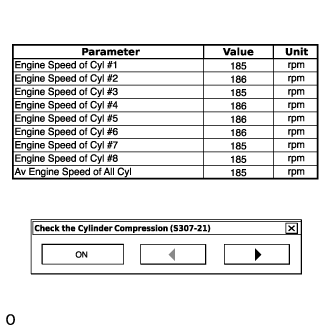
- HINT:
- At first, the GTS displays extremely high cylinder engine speed values. After approximately 10 seconds of engine cranking, each cylinder engine speed measurement will change to the actual engine speed.
- NOTICE:
- Do not crank the engine continuously for 20 seconds or more.
- If it is necessary to crank the engine again after Check the Cylinder Compression has been changed to ON and the engine has been cranked once, press Exit to return to the Active Test menu screen. Then change Check the Cylinder Compression to ON and crank the engine.
- Use a fully-charged battery.
- Stop cranking the engine, and then change "Check the Cylinder Compression" to OFF after the engine stops.
- NOTICE:
- If the Active Test is changed to OFF while the engine is being cranked, the engine will start.
- Push the snapshot button to turn the snapshot function off.
- Select "Stored Data" on the GTS screen, select the recorded data and display the data as a graph.
- HINT:
- If the data is not displayed as a graph, the change of the values cannot be observed.
- Check the change in engine speed values.
- HINT:
- As the data values of the Active Test return to their default values when cranking is stopped, the engine speed value of each cylinder cannot be observed. Therefore, it is necessary to use the data recorded with the snapshot function to check the engine speed values recorded during cranking.
- All fuel injectors are tested at the same time.
| SYSTEM CHECK |
- HINT:
- Performing a system check enables the system, which consists of multiple actuators, to be operated without removing any parts. In addition, it can show whether or not any DTCs are stored, and can detect potential malfunctions in the system. The system check can be performed with the GTS.
Connect the GTS to the DLC3.
Turn the ignition switch to ON.
Turn the GTS on.
Enter the following menus: Powertrain / Engine and ECT / Utility.
Perform the system check by referring to the table below.
Tester Display Test Part Control Range Diagnostic Note Secondary Air Injection Check (Automatic Mode) Perform secondary air injection system operation automatically With warm engine, ignition switch turned off once - If no pending DTCs are output after performing this test, the system is functioning normally.
- Refer to the inspection procedure for secondary air injection system DTCs.
- When performing Secondary Air Injection Check after the battery cable has been reconnected, wait for 7 minutes with the ignition switch turned to ON or the engine running.
- Turn the ignition switch off when System Check finishes.
Secondary Air Injection Check (Manual Mode) Perform 5 operations in order to operate secondary air injection system monitor manually With warm engine, ignition switch turned off once - Used to detect malfunctioning parts.
- Refer to the inspection procedure for secondary air injection system DTCs.
- When performing Secondary Air Injection Check after the battery cable has been reconnected, wait for 7 minutes with the ignition switch turned to ON or the engine running.
- Turn the ignition switch off when System Check finishes.
- If no pending DTCs are output after performing this test, the system is functioning normally.