Terminal No. (Symbols)
| Wiring Color
| Terminal Description
| Condition
| Specified Condition
|
A52*1-1 (BATT) - C46*1-81 (E1)
A38*2-1 (BATT) - C45*2-81 (E1)
| L - BR
| Battery (for measuring battery voltage and for ECM memory)
| Always
| 11 to 14 V
|
C46*1-41 (+BM) - C46*1-81 (E1)
C45*2-41 (+BM) - C45*2-81 (E1)
| P - BR
| Power source of throttle actuator
| Always
| 11 to 14 V
|
A52*1-28 (IGSW) - C46*1-81 (E1)
A38*2-28 (IGSW) - C45*2-81 (E1)
| B - BR
| Engine switch
| Engine switch on (IG)
| 11 to 14 V
|
A52*1-3 (+B) - C46*1-81 (E1)
A38*2-3 (+B) - C45*2-81 (E1)
| B - BR
| Power source of ECM
| Engine switch on (IG)
| 11 to 14 V
|
A52*1-2 (+B2) - C46*1-81 (E1)
A38*2-2 (+B2) - C45*2-81 (E1)
| B - BR
| Power source of ECM
| Engine switch on (IG)
| 11 to 14 V
|
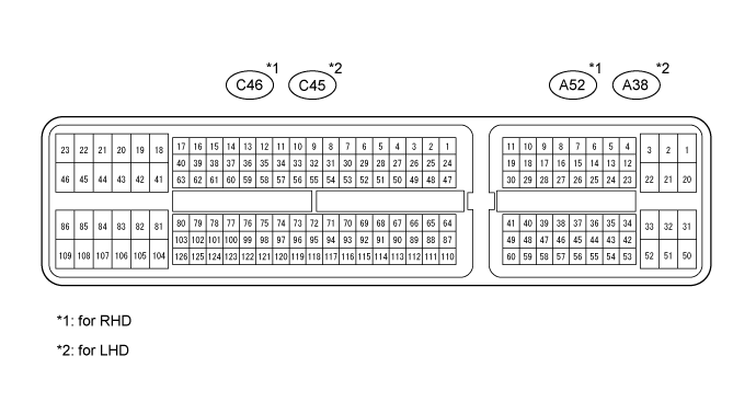
C46*1-58 (OC1+) - C46*1-57 (OC1-)
C45*2-58 (OC1+) - C45*2-57 (OC1-)
| B - L
| Camshaft timing oil control valve (OCV) (for Intake Side of Bank 1)
| Idling
| Pulse generation
(see waveform 1)
|
C46*1-52 (OC2+) - C46*1-51 (OC2-)
C45*2-52 (OC2+) - C45*2-51 (OC2-)
| L - R
| Camshaft timing oil control valve (OCV) (for Intake Side of Bank 2)
| Idling
| Pulse generation
(see waveform 1)
|
C46*1-56 (OE1+) - C46*1-55 (OE1-)
C45*2-56 (OE1+) - C45*2-55 (OE1-)
| W - B
| Camshaft timing oil control valve (OCV) (for Exhaust Side of Bank 1)
| Idling
| Pulse generation
(see waveform 1)
|
C46*1-50 (OE2+) - C46*1-49 (OE2-)
C45*2-50 (OE2+) - C45*2-49 (OE2-)
| R - B
| Camshaft timing oil control valve (OCV) (for Exhaust Side of Bank 2)
| Idling
| Pulse generation
(see waveform 1)
|
A52*1-34 (MREL) - C46*1-81 (E1)
A38*2-34 (MREL) - C45*2-81 (E1)
| V - BR
| EFI MAIN NO. 1 relay
| Engine switch on (IG)
| 11 to 14 V
|
C46*1-74 (VG) - C46*1-75 (E2G)
C45*2-74 (VG) - C45*2-75 (E2G)
| Y - W
| Mass air flow meter
| Idling, Shift lever position P or N, A/C switch OFF
| 0.5 to 3.0 V
|
C46*1-73 (THA) - C46*1-98 (E2)
C45*2-73 (THA) - C45*2-98 (E2)
| B - BR
| Intake air temperature sensor
| Idling, Intake air temperature 20°C (68°F)
| 0.5 to 3.4 V
|
C46*1-76 (THW) - C46*1-98 (E2)
C45*2-76 (THW) - C45*2-98 (E2)
| B - BR
| Engine coolant temperature sensor
| Idling, Engine coolant temperature 80°C (176°F)
| 0.2 to 1.0 V
|
C46*1-80 (VCTA) - C46*1-79 (ETA)
C45*2-80 (VCTA) - C45*2-79 (ETA)
| Y - L
| Power source of throttle position sensor (specific voltage)
| Engine switch on (IG)
| 4.5 to 5.5 V
|
C46*1-78 (VTA1) - C46*1-79 (ETA)
C45*2-78 (VTA1) - C45*2-79 (ETA)
| Y - L
| Throttle position sensor (for engine control)
| Engine switch on (IG),
Throttle valve fully closed
| 0.5 to 1.2 V
|
Engine switch on (IG),
Throttle valve fully open
| 3.2 to 4.8 V
|
C46*1-77 (VTA2) - C46*1-79 (ETA)
C45*2-77 (VTA2) - C45*2-79 (ETA)
| B - L
| Throttle position sensor (for sensor malfunction detection)
| Engine switch on (IG),
Throttle valve fully closed
| 2.1 to 3.1 V
|
Engine switch on (IG),
Throttle valve fully open
| 4.5 to 5.5 V
|
A52*1-55 (VPA) - A52*1-58 (EPA)
A38*2-55 (VPA) - A38*2-58 (EPA)
| R - W
| Accelerator pedal position sensor (for engine control)
| Engine switch on (IG),
Accelerator pedal released
| 0.5 to 1.1 V
|
Engine switch on (IG),
Accelerator pedal fully depressed
| 2.6 to 4.5 V
|
A52*1-56 (VPA2) - A52*1-60 (EPA2)
A38*2-56 (VPA2) - A38*2-60 (EPA2)
| GR - BE
| Accelerator pedal position sensor (for sensor malfunctioning detection)
| Engine switch on (IG),
Accelerator pedal released
| 1.2 to 2.0 V
|
Engine switch on (IG),
Accelerator pedal fully depressed
| 3.4 to 4.75 V
|
A52*1-57 (VCPA) - A52*1-58 (EPA)
A38*2-57 (VCPA) - A38*2-58 (EPA)
| L - W
| Power source of accelerator pedal position sensor (for VPA)
| Engine switch on (IG)
| 4.5 to 5.5 V
|
A52*1-59 (VCP2) - A52*1-60 (EPA2)
A38*2-59 (VCP2) - A38*2-60 (EPA2)
| V - BE
| Power source of accelerator pedal position sensor (for VPA2)
| Engine switch on (IG)
| 4.5 to 5.5 V
|
C46*1-22 (HA1A) - C46*1-23 (E04)
C45*2-22 (HA1A) - C45*2-23 (E04)
| L - W-B
| A/F sensor heater
| Idling
| Below 3.0 V
|
Engine switch on (IG)
| 11 to 14 V
|
C46*1-20 (HA2A) - C46*1-21 (E05)
C45*2-20 (HA2A) - C45*2-21 (E05)
| G - W-B
| A/F sensor heater
| Idling
| Below 3.0 V
|
Engine switch on (IG)
| 11 to 14 V
|
C46*1-126 (A1A+) - C46*1-81 (E1)
C45*2-126 (A1A+) - C45*2-81 (E1)
| G -BR
| A/F sensor
| Engine switch on (IG)
| 3.3 V*3
|
C46*1-125 (A1A-) - C46*1-81 (E1)
C45*2-125 (A1A-) - C45*2-81 (E1)
| R - BR
| A/F sensor
| Engine switch on (IG)
| 2.9 V*3
|
C46*1-103 (A2A+) - C46*1-81 (E1)
C45*2-103 (A2A+) - C45*2-81 (E1)
| P - BR
| A/F sensor
| Engine switch on (IG)
| 3.3 V*3
|
C46*1-102 (A2A-) - C46*1-81 (E1)
C45*2-102 (A2A-) - C45*2-81 (E1)
| L - BR
| A/F sensor
| Engine switch on (IG)
| 2.9 V*3
|
C46*1-45 (HT1B) - C46*1-46 (E03)
C45*2-45 (HT1B) - C45*2-46 (E03)
| G - W-B
| Heated oxygen sensor heater
| Idling
| Below 3.0 V
|
Engine switch on (IG)
| 11 to 14 V
|
C46*1-44 (HT2B) - C46*1-46 (E03)
C45*2-44 (HT2B) - C45*2-46 (E03)
| B - W-B
| Heated oxygen sensor heater
| Idling
| Below 3.0 V
|
Engine switch on (IG)
| 11 to 14 V
|
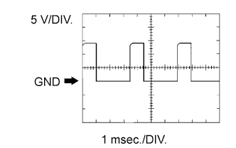
C46*1-114 (OX1B) - C46*1-115 (EX1B)
C45*2-114 (OX1B) - C45*2-115 (EX1B)
| G - L
| Heated oxygen sensor
| Engine speed maintained at 2500 rpm for 2 minutes after warming up sensor
| Pulse generation
(see waveform 2)
|
C46*1-112 (OX2B) - C46*1-113 (EX2B)
C45*2-112 (OX2B) - C45*2-113 (EX2B)
| R - W
| Heated oxygen sensor
| Engine speed maintained at 2500 rpm for 2 minutes after warming up sensor
| Pulse generation
(see waveform 2)
|
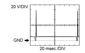
C46*1-86 (#10) - C46*1-43 (E01)
C45*2-86 (#10) - C45*2-43 (E01)
| R - W-B
| Injector
| Engine switch on (IG)
| 11 to 14 V
|
Idling
| Pulse generation
(see waveform 3)
|
C46*1-109 (#20) - C46*1-43 (E01)
C45*2-109 (#20) - C45*2-43 (E01)
| L - W-B
| Injector
| Engine switch on (IG)
| 11 to 14 V
|
Idling
| Pulse generation
(see waveform 3)
|
C46*1-85 (#30) - C46*1-43 (E01)
C45*2-85 (#30) - C45*2-43 (E01)
| R - W-B
| Injector
| Engine switch on (IG)
| 11 to 14 V
|
Idling
| Pulse generation
(see waveform 3)
|
C46*1-108 (#40) - C46*1-43 (E01)
C45*2-108 (#40) - C45*2-43 (E01)
| Y - W-B
| Injector
| Engine switch on (IG)
| 11 to 14 V
|
Idling
| Pulse generation
(see waveform 3)
|
C46*1-84 (#50) - C46*1-43 (E01)
C45*2-84 (#50) - C45*2-43 (E01)
| G - W-B
| Injector
| Engine switch on (IG)
| 11 to 14 V
|
Idling
| Pulse generation
(see waveform 3)
|
C46*1-107 (#60) - C46*1-43 (E01)
C45*2-107 (#60) - C45*2-43 (E01)
| R - W-B
| Injector
| Engine switch on (IG)
| 11 to 14 V
|
Idling
| Pulse generation
(see waveform 3)
|
C46*1-83 (#70) - C46*1-43 (E01)
C45*2-83 (#70) - C45*2-43 (E01)
| W - W-B
| Injector
| Engine switch on (IG)
| 11 to 14 V
|
Idling
| Pulse generation
(see waveform 3)
|
C46*1-106 (#80) - C46*1-43 (E01)
C45*2-106 (#80) - C45*2-43 (E01)
| R - W-B
| Injector
| Engine switch on (IG)
| 11 to 14 V
|
Idling
| Pulse generation
(see waveform 3)
|
C46*1-94 (KNK1) - C46*1-93 (EKNK)
C45*2-94 (KNK1) - C45*2-93 (EKNK)
| R - G
| Knock sensor
| Engine speed maintained at 4000 rpm after warming up engine
| Pulse generation
(see waveform 4)
|
C46*1-117 (KNK2) - C46*1-116 (EKN2)
C45*2-117 (KNK2) - C45*2-116 (EKN2)
| W - B
| Knock sensor
| Engine speed maintained at 4000 rpm after warming up engine
| Pulse generation
(see waveform 4)
|
C46*1-96 (KNK3) - C46*1-95 (EKN3)
C45*2-96 (KNK3) - C45*2-95 (EKN3)
| W - B
| Knock sensor
| Engine speed maintained at 4000 rpm after warming up engine
| Pulse generation
(see waveform 4)
|
C46*1-119 (KNK4) - C46*1-118 (EKN4)
C45*2-119 (KNK4) - C45*2-118 (EKN4)
| R - G
| Knock sensor
| Engine speed maintained at 4000 rpm after warming up engine
| Pulse generation
(see waveform 4)
|
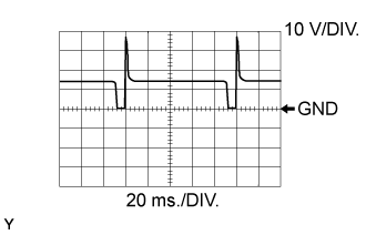
C46*1-92 (VV1+) - C46*1-91 (VV1-)
C45*2-92 (VV1+) - C45*2-91 (VV1-)
| R - Y
| Variable valve timing (VVT) sensor (for Intake Side of Bank 1)
| Idling
| Pulse generation
(see waveform 5)
|
C46*1-87 (VV2+) - C46*1-88 (VV2-)
C45*2-87 (VV2+) - C45*2-88 (VV2-)
| R - Y
| Variable valve timing (VVT) sensor (for Intake Side for Bank 2)
| Idling
| Pulse generation
(see waveform 5)
|
C46*1-69 (EV1+) - C46*1-68 (EV1-)
C45*2-69 (EV1+) - C45*2-68 (EV1-)
| L - Y
| Variable valve timing (VVT) sensor (for Exhaust Side of Bank 1)
| Idling
| Pulse generation
(see waveform 16)
|
C46*1-64 (EV2+) - C46*1-65 (EV2-)
C45*2-64 (EV2+) - C45*2-65 (EV2-)
| L - Y
| Variable valve timing (VVT) sensor (for Exhaust Side of Bank 2)
| Idling
| Pulse generation
(see waveform 16)
|
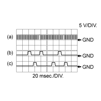
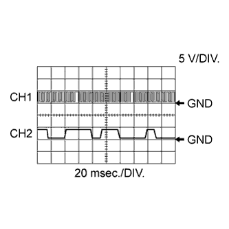
C46*1-110 (NE+) - C46*1-111 (NE-)
C45*2-110 (NE+) - C45*2-111 (NE-)
| W - Y
| Crankshaft position sensor
| Idling
| Pulse generation
(see waveform 5)
|
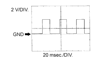
C46*1-40 (IGT1) - C46*1-81 (E1)
C45*2-40 (IGT1) - C45*2-81 (E1)
| Y - BR
| Ignition coil (ignition signal)
| Idling
| Pulse generation
(see waveform 6)
|
C46*1-33 (IGT2) - C46*1-81 (E1)
C45*2-33 (IGT2) - C45*2-81 (E1)
| L - BR
| Ignition coil (ignition signal)
| Idling
| Pulse generation
(see waveform 6)
|
C46*1-37 (IGT3) - C46*1-81 (E1)
C45*2-37 (IGT3) - C45*2-81 (E1)
| B - BR
| Ignition coil (ignition signal)
| Idling
| Pulse generation
(see waveform 6)
|
C46*1-34 (IGT4) - C46*1-81 (E1)
C45*2-34 (IGT4) - C45*2-81 (E1)
| L - BR
| Ignition coil (ignition signal)
| Idling
| Pulse generation
(see waveform 6)
|
C46*1-35 (IGT5) - C46*1-81 (E1)
C45*2-35 (IGT5) - C45*2-81 (E1)
| G - BR
| Ignition coil (ignition signal)
| Idling
| Pulse generation
(see waveform 6)
|
C46*1-36 (IGT6) - C46*1-81 (E1)
C45*2-36 (IGT6) - C45*2-81 (E1)
| P - BR
| Ignition coil (ignition signal)
| Idling
| Pulse generation
(see waveform 6)
|
C46*1-38 (IGT7) - C46*1-81 (E1)
C45*2-38 (IGT7) - C45*2-81 (E1)
| W - BR
| Ignition coil (ignition signal)
| Idling
| Pulse generation
(see waveform 6)
|
C46*1-39 (IGT8) - C46*1-81 (E1)
C45*2-39 (IGT8) - C45*2-81 (E1)
| G - BR
| Ignition coil (ignition signal)
| Idling
| Pulse generation
(see waveform 6)
|
C46*1-105 (IGF1) - C46*1-81 (E1)
C45*2-105 (IGF1) - C45*2-81 (E1)
| G - BR
| Ignition coil (ignition confirmation signal)
| Engine switch on (IG)
| 4.5 to 5.5 V
|
Idling
| Pulse generation
(see waveform 6)
|
C46*1-104 (IGF2) - C46*1-81 (E1)
C45*2-104 (IGF2) - C45*2-81 (E1)
| R - BR
| Ignition coil (ignition confirmation signal)
| Engine switch on (IG)
| 4.5 to 5.5 V
|
Idling
| Pulse generation
(see waveform 6)
|
C46*1-63 (PRG) - C46*1-81 (E1)
C45*2-63 (PRG) - C45*2-81 (E1)
| B - BR
| Purge VSV
| Engine switch on (IG)
| 11 to 14 V
|
Idling
| Pulse generation
(see waveform 7)
|
A52*1-13 (SPD) - C46*1-81 (E1)
A38*2-13 (SPD) - C45*2-81 (E1)
| L - BR
| Speed signal from combination meter
| Driving at 20 km/h (12 mph)
| Pulse generation
(see waveform 8)
|
A52*1-46 (STA) - C46*1-81 (E1)
A38*2-46 (STA) - C45*2-81 (E1)
| R - BR
| Starter signal
| Cranking
| 5.5 V or more
|
C46*1-120 (NSW) - C46*1-81 (E1)
C45*2-120 (NSW) - C45*2-81 (E1)
| L - BR
| Park / neutral position switch
| Engine switch on (IG), Shift lever position other than P and N
| 11 to 14 V
|
Engine switch on (IG), Shift lever position in P or N
| Below 3.0 V
|
A52*1-36 (STP) - C46*1-81 (E1)
A38*2-36 (STP) - C45*2-81 (E1)
| R - BR
| Stop light switch
| Brake pedal depressed
| 7.5 to 14 V
|
Brake pedal released
| Below 1.5 V
|
A52*1-35 (ST1-) - C46*1-81 (E1)
A38*2-35 (ST1-) - C45*2-81 (E1)
| P - BR
| Stop light switch
(opposite to STP terminal)
| Engine switch on (IG),
Brake pedal depressed
| Below 1.5 V
|
Engine switch on (IG),
Brake pedal released
| 7.5 to 14 V
|
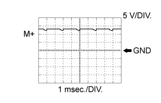
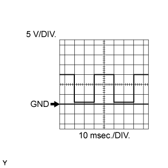
C46*1-19 (M+) - C46*1-82 (ME01)
C45*2-19 (M+) - C45*2-82 (ME01)
| R - W-B
| Throttle actuator
| Idling with warm engine
| Pulse generation
(see waveform 9)
|
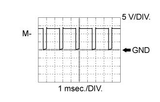
C46*1-18 (M-) - C46*1-82 (ME01)
C45*2-18 (M-) - C45*2-82 (ME01)
| G - W-B
| Throttle actuator
| Idling with warm engine
| Pulse generation
(see waveform 10)
|
A52*1-52 (FPC) - C46*1-81 (E1)
A38*2-52 (FPC) - C45*2-81 (E1)
| W - BR
| Fuel pump control
| Engine switch on (IG)
| Below 1.5 V
|
A52*1-16 (TC) - C46*1-81 (E1)
A38*2-16 (TC) - C45*2-81 (E1)
| V - BR
| Terminal TC of DLC3
| Engine switch on (IG)
| 11 to 14 V
|
A52*1-15 (TACH) - C46*1-81 (E1)
A38*2-15 (TACH) - C45*2-81 (E1)
| W - BR
| Engine speed
| Idling
| Pulse generation
(see waveform 11)
|
C46*1-67 (VCV1) - C46*1-98 (E2)
C45*2-67 (VCV1) - C45*2-98 (E2)
| L - BR
| Power source for sensor (specific voltage)
| Engine switch on (IG)
| 4.5 to 5.5 V
|
C46*1-66 (VCV2) - C46*1-98 (E2)
C45*2-66 (VCV2) - C45*2-98 (E2)
| L - BR
| Power source for sensor (specific voltage)
| Engine switch on (IG)
| 4.5 to 5.5 V
|
C46*1-32 (ALT) - C46*1-81 (E1)
C45*2-32 (ALT) - C45*2-81 (E1)
| R - BR
| Generator
| Engine switch on (IG)
| 11 to 14 V
|
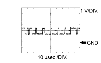
A52*1-10 (CANH) - C46*1-81 (E1)
A38*2-10 (CANH) - C45*2-81 (E1)
| V - BR
| CAN communication line
| Engine switch on (IG)
| Pulse generation
(see waveform 12)
|
A52*1-11 (CANL) - C46*1-81 (E1)
A38*2-11 (CANL) - C45*2-81 (E1)
| W - BR
| CAN communication line
| Engine switch on (IG)
| Pulse generation
(see waveform 13)
|
C46*1-62 (ACIS) - C46*1-81 (E1)
C45*2-62 (ACIS) - C45*2-81 (E1)
| L - BR
| VSV for ACIS (Acoustic Control Induction System) operation signal
| Engine switch on (IG)
| 11 to 14 V
|
C46*1-28 (AIRV) - C46*1-81 (E1)
C45*2-28 (AIRV) - C45*2-81 (E1)
| BR - BR
| Air switching valve signal for secondary air injection system
| Engine switch on (IG)
| 11 to 14 V
|
C46*1-54 (AIRP) - C46*1-81 (E1)
C45*2-54 (AIRP) - C45*2-81 (E1)
| P - BR
| Air pump control signal for secondary air injection system
| Engine switch on (IG)
| 11 to 14 V
|
C46*1-30 (AIDI) - C46*1-81 (E1)
C45*2-30 (AIDI) - C45*2-81 (E1)
| G - BR
| Diagnostic information signal for secondary air injection system
| Air injection system operates
| Pulse generation
(see waveform 15)
|
A52*1-54 (AIP) - C46*1-98 (E2)
A38*2-54 (AIP) - C45*2-98 (E2)
| P - BR
| Secondary air injection system pressure signal
| Engine switch on (IG)
| 3.0 to 3.6 V
|
A52*1-53 (AIP2) - C46*1-98 (E2)
A38*2-53 (AIP2) - C45*2-98 (E2)
| L - BR
| Secondary air injection system pressure signal
| Engine switch on (IG)
| 3.0 to 3.6 V
|
C46*1-60 (HAI1) - C46*1-81 (E1)
C45*2-60 (HAI1) - C45*2-81 (E1)
| G - BR
| Air pump heater for secondary air injection system
| AI heater operating
| Below 1.5 V
|
C46*1-61 (AIR1) - C46*1-81 (E1)
C45*2-61 (AIR1) - C45*2-81 (E1)
| R - BR
| Air pump for secondary air injection system
| AI operating
| 11 to 14 V
|
C46*1-90 (G2) - C46*1- 89 (G2-)
C45*2-90 (G2) - C45*2- 89 (G2-)
| G - Y
| Camshaft position sensor
| Idling
| Pulse generation
(see waveform 14)
|
C46*1-72 (PSP) - C46*1-98 (E2)
C45*2-72 (PSP) - C45*2-98 (E2)
| G - BR
| Power steering oil pressure switch
| Engine switch on (IG)
| 0.5 to 4.5 V
|
C46*1-97 (PIM) - C46*1-98 (E2)
C45*2-97 (PIM) - C45*2-98 (E2)
| L - BR
| Manifold absolute pressure sensor
| Idling
| 1.2 to 2.0 V
|
A52*1-17 (ACT) - C46*1-81 (E1)
A38*2-17 (ACT) - C45*2-81 (E1)
| G - BR
| A/C signal
| A/C on
| 11 to 14 V
|
A/C off
| Below 1.5 V
|
A52*1-19 (AC1) - C46*1-81 (E1)
A38*2-19 (AC1) - C45*2-81 (E1)
| L - BR
| A/C signal
| A/C on
| Below 1.5 V
|
A/C off
| 11 to 14 V
|
A52*1-7 (NEO) - C46*1-81 (E1)
A38*2-7 (NEO) - C45*2-81 (E1)
| L - BR
| Engine speed signal
| Idle after engine warmed up
| Pulse generation
(see waveform 17)
|