Fuel injector 2AD-FHV
Components
Fuel injector 2AD-FHV
On-vehicle inspection
-
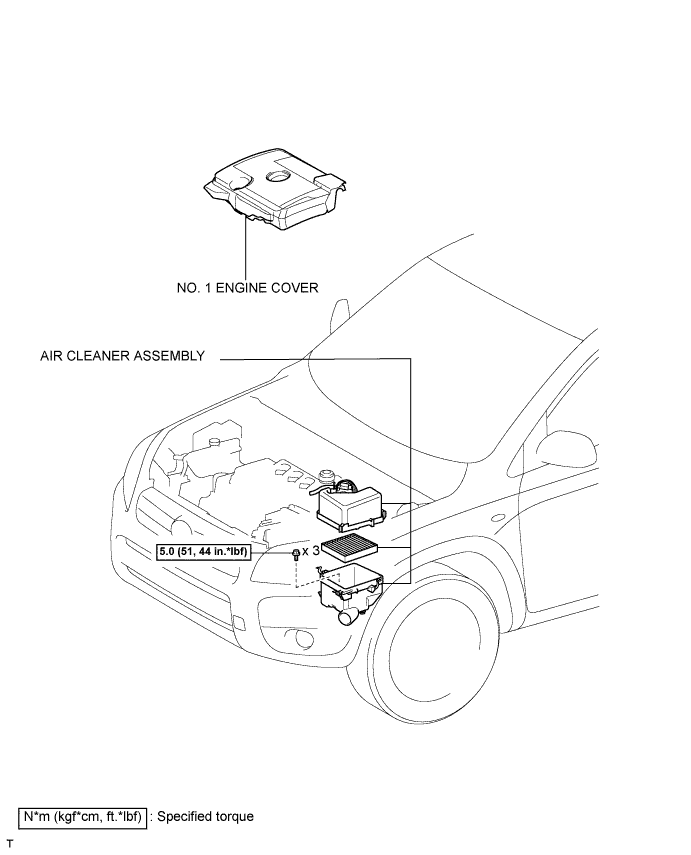
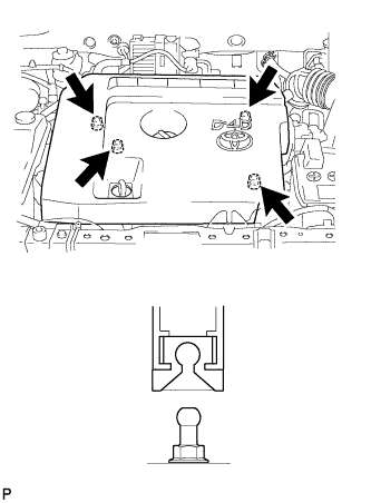
Detach the 4 clips and remove the engine cover.
-
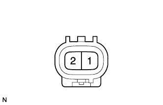
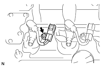
Disconnect the injector connector.
-
Measure the resistance.
Standard resistance:
Tester Connection Condition Specified Condition 1 - 2 20°C (68°F) 0.9 to 1.1 M? HINT:
The temperature indicated in "Condition" is the temperature of the injector assembly.
If the result is not as specified, replace the injector assembly. -
Connect the injector connector.
-
Attach the 4 clips to install the engine cover.
Fuel injector 2AD-FHV
Removal
CAUTION:
Wait at least 90 seconds after disconnecting the cable from the negative (-) battery terminal to prevent airbag and seat belt pretensioner activation.
-
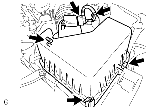
Detach the 4 clips and remove the engine cover.
-
Disconnect the mass air flow meter connector.
-
Unhook the 3 hook clamps.
-
Disengage the wire harness clamp.
-
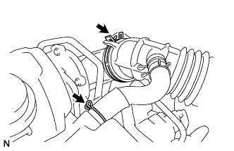
Using pliers, grip the claws of the clip and slide the clip to disconnect the PCV hose from the cylinder head cover.
-
Using pliers, grip the claws of the clip to remove the air cleaner cap.
-
Remove the air filter element.
-
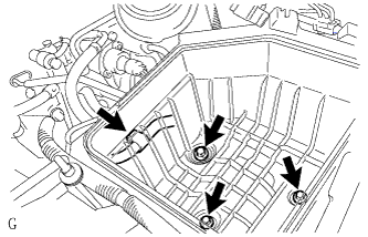
Disconnect the wire harness clamp and remove the 3 bolts and air cleaner case.
-
Disconnect the fuel pressure sensor connector.
-
Disconnect the pressure discharge valve connector.
-
Disconnect the turbo pressure sensor connector.
-
Remove the grommet and nut and disconnect the wire harness.
-
Remove the 2 nuts and disconnect the engine wire from the engine cover bracket.
NOTICE:
After removing the fuel pipe, to prevent dirt or foreign objects from entering the pipe inlet, cover the common rail with electrical tape. Also protect the injector inlets with electrical tape or plastic bags.
-
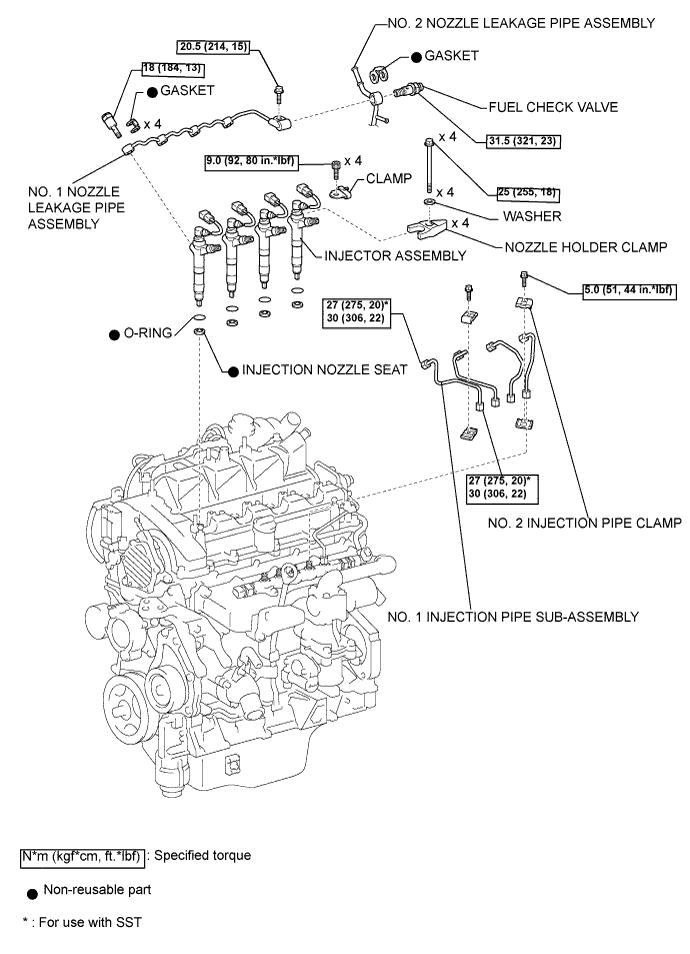
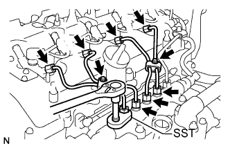
Remove the 2 bolts and 4 injection pipe clamps.
-
Using SST, loosen the 4 nuts at the common rail end of the injection pipes.
SST:
09023-38401
-
Using SST, loosen the 4 nuts at the injector end of the injection pipes.
SST:
09023-38401
-
Remove the 4 injection pipes.
-
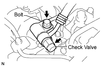
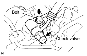
Remove the fuel check valve, bolt and gasket.
-
Remove the 4 union bolts, 4 gaskets and No. 1 nozzle leakage pipe.
-
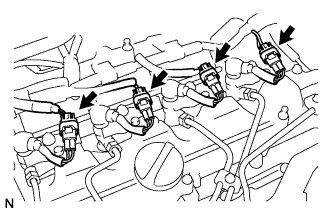
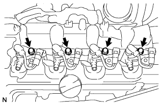
Disconnect the 4 injector connectors.
-
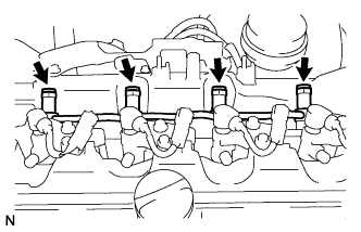
Using a hexagon socket wrench, remove the 4 bolts.
-
Remove the 4 bolts, 4 washers and 4 nozzle holder clamps.
-
Remove the 4 injectors and 4 injection nozzle seats from the cylinder head.
-
Remove the O-rings from each injector.
NOTICE:
When removing the injector assembly, store them in the correct order so that they can be returned to their original locations when reassembling.
Fuel injector 2AD-FHV
Installation
NOTICE:
Before installing the injector, check for carbon, foreign matter, etc. on the seal surfaces of the cylinder head and injector. If there is foreign matter, remove it before installing the injector.
-
Install 4 new nozzle seats to the cylinder head.
-
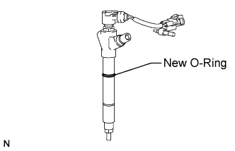
Install new O-rings to each injector.
-
Apply a light coat of engine oil to the O-rings on each injector.
-
Install the 4 injectors to the cylinder head.
NOTICE:
Fit the injectors to the nozzle seats.
-
Temporarily install the 4 clamps to the cylinder head with the 4 bolts.
-
Using a hexagon socket wrench, tighten the 4 bolts.
Torque:
9 N*m{ 92 kgf*cm , 80 lbsf.in }
-
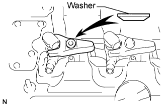
Install the nozzle holder clamps and washers as shown in the illustration.
-
Temporarily install the nozzle holder clamp bolts.
NOTICE:
- Pay attention to the mounting orientation (beveled edge) of the washer.
- When temporarily attaching the nozzle holder clamp and the nozzle holder clamp bolt, be careful not to position them at an angle.
HINT:
Apply a light coat of engine oil on the threads of the nozzle holder clamp bolts.
-
Temporarily install the No. 1, No. 2, No. 3 and No. 4 injection pipe.
-
Temporarily install 4 new gaskets and the No. 1 leakage pipe with the 4 union bolts.
-
Tighten the 4 nozzle holder clamp bolts.
Torque:
25 N*m{ 255 kgf*cm , 18 ft.*lbf }
-
Temporarily install a new gasket, fuel check valve and bolt.
-
Tighten the 4 union bolts.
Torque:
18 N*m{ 184 kgf*cm , 13 ft.*lbf }
-
Tighten the fuel check valve and bolt.
Torque:
31.5 N*m{ 321 kgf*cm , 23 ft.*lbf } for fuel check valve
20.5 N*m{ 209 kgf*cm , 15 ft.*lbf } for bolt
NOTICE:
- In a case where an injector is replaced, the injection pipes must also be replaced.
-
Temporarily install the 4 injection pipes.
-
Using SST, tighten the 4 nuts at the common rail end of the injection pipes.
SST:
09023-38401
Torque:
27 N*m{ 275 kgf*cm , 20 ft.*lbf }
HINT:
- Use of the proper SST is required to ensure that the correct torque is applied to the injection pipe nut.
- Use a torque wrench with a fulcrum length of 30 cm (11.81 in.).
- Make sure that the pipe is not deformed or twisted during installation.
If the pipe is deformed or twisted, or if it cannot be installed properly, replace the pipe with a new pipe.
-
Using SST, tighten the 4 nuts at the injector end of the injection pipes.
SST:
09023-38401
Torque:
27 N*m{ 275 kgf*cm , 20 ft.*lbf }
HINT:
- Use of the proper SST is required to ensure that the correct torque is applied to the injection pipe nut.
- Use a torque wrench with a fulcrum length of 30 cm (11.81 in.).
- Make sure that the pipe is not deformed or twisted during installation.
If the pipe is deformed or twisted, or if it cannot be installed properly, replace the pipe with a new pipe.
-
Connect the engine wire to the engine cover bracket.
-
Connect the glow plug wire harness.
-
Install the 2 nuts.
-
Install the nut and grommet.
Torque:
2.2 N*m{ 22 kgf*cm , 19 lbsf.in }
-
Connect the turbo pressure sensor connector.
-
Connect the discharge valve connector.
-
Connect the fuel pressure sensor connector.
-
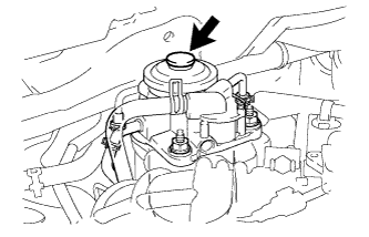
Using the hand pump indicated by the arrows in the illustration, bleed the fuel system. Continue pumping until pumping becomes difficult.
-
Attach the 4 clips to install the engine cover.
HINT:
Each injector assembly has a characteristic fuel injecting behavior.
-
Perform the ACTIVE TEST.
-
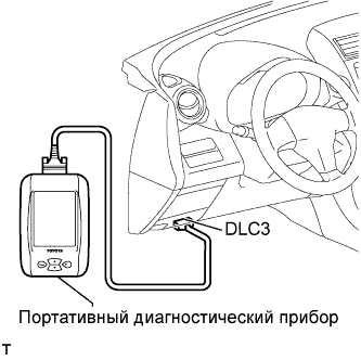
Connect the intelligent tester to the DLC3.
-
Turn the ignition switch on (IG).
-
Turn the intelligent tester ON.
-
Enter the following menus: Powertrain / Engine / Active Test.
-
Perform the Active Test.
Intelligent Tester Display Test Details Control Range Diagnostic Notes Test the Fuel Leak Pressurizing common rail internal fuel pressure, and checking for fuel leaks Stop/Start - Fuel pressure inside common rail pressurized to specified value and engine speed increased to 2,000 rpm when Start is selected
- Above conditions to be maintained while test is Start
-