DESCRIPTION
WIRING DIAGRAM
INSPECTION PROCEDURE
CLEAR DTC
CHECK FOR DTC
READ VALUE USING TECHSTREAM (IMMOBILISER FUEL CUT)
CHECK THEFT WARNING INDICATOR LIGHT OPERATION
CHECK THEFT WARNING INDICATOR LIGHT OPERATION
CHECK WHETHER ENGINE STARTS WITH OTHER KEYS
CHECK TRANSPONDER KEY AMPLIFIER (VC5 SIGNAL)
CHECK HARNESS AND CONNECTOR (TRANSPONDER KEY AMPLIFIER - TRANSPONDER KEY ECU ASSEMBLY, IG TERMINAL VOLTAGE)
CHECK TRANSPONDER KEY AMPLIFIER (TXCT SIGNAL)
CHECK HARNESS AND CONNECTOR (TRANSPONDER KEY AMPLIFIER - TRANSPONDER KEY ECU ASSEMBLY)
CHECK TRANSPONDER KEY AMPLIFIER (CODE SIGNAL)
CHECK HARNESS AND CONNECTOR (TRANSPONDER KEY AMPLIFIER - TRANSPONDER KEY ECU ASSEMBLY)
REPLACE TRANSPONDER KEY AMPLIFIER
CHECK WHETHER ENGINE STARTS
REPLACE TRANSPONDER KEY ECU ASSEMBLY
REGISTER KEY
REGISTER ECU COMMUNICATION ID
CHECK WHETHER ENGINE STARTS
REPLACE KEY
REREGISTER KEY
CHECK WHETHER ENGINE STARTS
ENGINE IMMOBILISER SYSTEM (for Hatchback) - Engine does not Start because No Initial Combustion |
DESCRIPTION
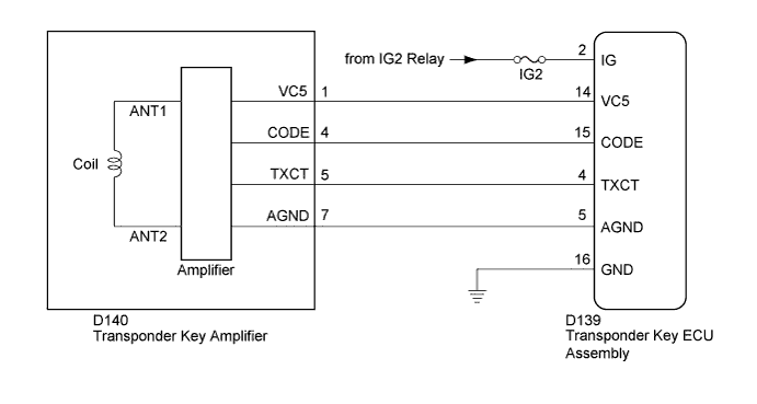
- When the key is inserted into the ignition key cylinder, the antenna coil receives the key code. Then the amplifier amplifies the ID code and outputs it to the transponder key ECU assembly.
- If this symptom occurs, there may be a communication problem between the transponder key amplifier and the transponder key ECU assembly.
WIRING DIAGRAM
INSPECTION PROCEDURE
- NOTICE:
- When replacing the key and transponder key ECU assembly, refer to the Registration (YARIS_NCP93 RM00000120Y021X.html).
- Inspection the fuses for circuits related to this system before performing the following inspection procedure.
Clear the DTCs (YARIS_NCP93 RM000001TCQ01OX.html).
Check for DTCs (YARIS_NCP93 RM000001TCQ01OX.html).
- HINT:
- Before checking for DTCs, perform the "DTC Output Confirmation Operation" procedure.
ResultResult
| Proceed to
|
No DTC output
| A
|
DTC output
| B
|
| 3.READ VALUE USING TECHSTREAM (IMMOBILISER FUEL CUT) |
Turn the ignition switch off.
Connect the Techstream to the DLC3.
Turn the ignition switch to ON.
Turn the Techstream on.
Enter the following menus: Powertrain / Engine and ECT / Data List.
Engine and ECTTester Display
| Measurement Item/Range
| Normal Condition
| Diagnostic Note
|
Immobiliser Fuel Cut
| Status of immobiliser fuel cut/
ON or OFF
| -
| -
|
- OK:
- The item in the Data List indicates "OFF"
ResultResult
| Proceed to
|
NG
| A
|
OK
| B
|
| 4.CHECK THEFT WARNING INDICATOR LIGHT OPERATION |
When the key inserted in ignition key cylinder, check that the theft warning indicator light assembly off.
- OK:
- The theft warning indicator light assembly off.
| 5.CHECK THEFT WARNING INDICATOR LIGHT OPERATION |
Perform inspection using a different key that has been registered to the vehicle.
When the key inserted in ignition key cylinder, check that the theft warning indicator light assembly off.
- OK:
- The theft warning indicator light assembly off.
| 6.CHECK WHETHER ENGINE STARTS WITH OTHER KEYS |
Perform inspection using a different key that has been registered to the vehicle.
It leaves for 5 seconds by the ignition switch ON status, and the engine starting operation is done.
ResultResult
| Proceed to
|
Engine can not be started
| A
|
Engine can be started
| B
|
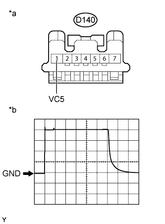
| 7.CHECK TRANSPONDER KEY AMPLIFIER (VC5 SIGNAL) |
Disconnect the D140 transponder key amplifier connector.
Using an oscilloscope, check the waveform.
Waveform
Measurement ConditionItem
| Content
|
Tester Connection
| D140-1 (VC5) - Body ground
|
Tool Setting
| 1 V/DIV., 20 ms./DIV.
|
Condition
| Key inserted in ignition key cylinder
|
- OK:
- Waveform is output normally (refer to illustration).
Text in Illustration*a
| Front view of wire harness connector
(to Transponder Key Amplifier)
|
*b
| Waveform
|
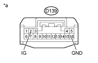
| 8.CHECK HARNESS AND CONNECTOR (TRANSPONDER KEY AMPLIFIER - TRANSPONDER KEY ECU ASSEMBLY, IG TERMINAL VOLTAGE) |
Disconnect the D140 transponder key amplifier connector.
Disconnect the D139 transponder key ECU assembly connector.
Measure the resistance according to the value(s) in the table below.
- Standard Resistance:
Tester Connection
| Condition
| Specified Condition
|
D140-1 (VC5) - D139-14 (VC5)
| Always
| Below 1 Ω
|
D140-7 (AGND) - D139-5 (AGND)
| Always
| Below 1 Ω
|
D140-1 (VC5) - Body ground
| Always
| 10 kΩ or higher
|
Reconnect the transponder key amplifier connector.
Measure the voltage according to the value(s) in the table below.
- Standard Voltage:
Tester Connection
| Switch Condition
| Specified Condition
|
D139-2 (IG) - D139-16 (GND)
| Ignition switch ON
| 11 to 14 V
|
Text in Illustration*a
| Front view of wire harness connector
(to Transponder Key ECU assembly)
|
ResultResult
| Proceed to
|
OK
| A
|
NG (Wire harness or connector)
| B
|
NG (IG terminal voltage)
| C
|
| | REPAIR OR REPLACE HARNESS OR CONNECTOR |
|
|
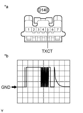
| 9.CHECK TRANSPONDER KEY AMPLIFIER (TXCT SIGNAL) |
Disconnect the D140 transponder key amplifier connector.
Using an oscilloscope, check the waveform.
Waveform
Measurement ConditionItem
| Content
|
Tester Connection
| D140-5 (TXCT) - Body ground
|
Tool Setting
| 1 V/DIV., 20 ms./DIV.
|
Condition
| Key inserted in ignition key cylinder
|
- OK:
- Waveform is output normally (refer to illustration).
Text in Illustration*a
| Front view of wire harness connector
(to Transponder Key Amplifier)
|
*b
| Waveform
|
| 10.CHECK HARNESS AND CONNECTOR (TRANSPONDER KEY AMPLIFIER - TRANSPONDER KEY ECU ASSEMBLY) |
Disconnect the D140 transponder key amplifier connector.
Disconnect the D139 transponder key ECU assembly connector.
Measure the resistance according to the value(s) in the table below.
- Standard Resistance:
Tester Connection
| Condition
| Specified Condition
|
D140-5 (TXCT) - D139-4 (TXCT)
| Always
| Below 1 Ω
|
D140-5 (TXCT) - Body ground
| Always
| 10 kΩ or higher
|
| | REPAIR OR REPLACE HARNESS OR CONNECTOR |
|
|
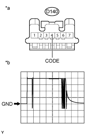
| 11.CHECK TRANSPONDER KEY AMPLIFIER (CODE SIGNAL) |
Disconnect the D140 transponder key amplifier connector.
Using an oscilloscope, check the waveform.
Waveform
Measurement ConditionItem
| Content
|
Tester Connection
| D140-4 (CODE) - Body ground
|
Tool Setting
| 1 V/DIV., 20 ms./DIV.
|
Condition
| Key inserted in ignition key cylinder
|
- OK:
- Waveform is output normally (refer to illustration).
Text in Illustration*a
| Front view of wire harness connector
(to Transponder Key Amplifier)
|
*b
| Waveform
|
| 12.CHECK HARNESS AND CONNECTOR (TRANSPONDER KEY AMPLIFIER - TRANSPONDER KEY ECU ASSEMBLY) |
Disconnect the D140 transponder key amplifier connector.
Disconnect the D139 transponder key ECU assembly connector.
Measure the resistance according to the value(s) in the table below.
- Standard Resistance:
Tester Connection
| Condition
| Specified Condition
|
D140-4 (CODE) - D139-15 (CODE)
| Always
| Below 1 Ω
|
D140-4 (CODE) - Body ground
| Always
| 10 kΩ or higher
|
Reconnect the transponder key ECU assembly connector.
Reconnect the transponder key amplifier connector.
Using an oscilloscope, check the waveform.
Waveform
Measurement ConditionItem
| Content
|
Tester Connection
| D140-4 (CODE) - Body ground
|
Tool Setting
| 1 V/DIV., 20 ms./DIV.
|
Condition
| Key inserted in ignition key cylinder
|
- OK:
- Waveform is output normally (refer to illustration).
Text in Illustration*a
| Front view of wire harness connector
(to Transponder Key Amplifier)
|
*b
| Waveform
|
ResultResult
| Proceed to
|
Terminal CODE stuck high (5 V)
| A
|
Terminal CODE stuck low (1 V or less)
| B
|
Problem in wire harness or connector
| C
|
| |
|
| | REPAIR OR REPLACE HARNESS OR CONNECTOR |
|
|
| 13.REPLACE TRANSPONDER KEY AMPLIFIER |
Replace the transponder key amplifier (YARIS_NCP93 RM000003RZI00HX.html).
| 14.CHECK WHETHER ENGINE STARTS |
Check that the engine starts with an already registered vehicle key.
- OK:
- Engine starts normally.
| OK |
|
|
|
| END (TRANSPONDER KEY AMPLIFIER WAS DEFECTIVE) |
|
| 15.REPLACE TRANSPONDER KEY ECU ASSEMBLY |
Replace the transponder key ECU assembly with a new one (YARIS_NCP93 RM000004E7M008X.html).
Register the key (YARIS_NCP93 RM00000120Y021X.html).
| 17.REGISTER ECU COMMUNICATION ID |
Register the ECU communication ID (YARIS_NCP93 RM00000120Y021X.html).
| 18.CHECK WHETHER ENGINE STARTS |
Check that the engine starts with an already registered vehicle key.
- OK:
- Engine starts normally.
| OK |
|
|
|
| END (TRANSPONDER KEY ECU ASSEMBLY WAS DEFECTIVE) |
|
Replace the transponder key master transmitter with a new one (YARIS_NCP93 RM00000120Y021X.html).
Reregister the key (YARIS_NCP93 RM00000120Y021X.html).
| 21.CHECK WHETHER ENGINE STARTS |
Check that the engine starts with an already registered vehicle key.
- OK:
- Engine starts normally.
| OK |
|
|
|
| END (KEY (TRANSPONDER KEY MASTER TRANSMITTER) WAS DEFECTIVE) |
|