Dtc C1553 Pig Power Supply Overvoltage
DESCRIPTION
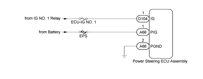
WIRING DIAGRAM
INSPECTION PROCEDURE
CHECK HARNESS AND CONNECTOR (IG)
CHECK HARNESS AND CONNECTOR (POWER STEERING ECU ASSEMBLY - BODY GROUND)
DTC C1553 PIG Power Supply Overvoltage |
DESCRIPTION
If the power steering ECU assembly determines that the motor power source voltage and the IG voltage are not within the specified range, it stops the power assist as a fail-safe function.DTC No.
| DTC Detection Condition
| Trouble Area
|
C1553
| - PIG power source overvoltage
- IG power source overvoltage
| - IG and PIG power source circuits
- Power steering ECU assembly
|
WIRING DIAGRAM
INSPECTION PROCEDURE
- NOTICE:
- If the power steering ECU assembly has been replaced, perform the torque sensor zero point calibration and assist map writing (YARIS_NCP93 RM000000OSZ018X.html).
- Inspect the fuses for circuits related to this system before performing the following inspection procedure.
| 1.CHECK HARNESS AND CONNECTOR (IG) |
Disconnect the power steering ECU assembly connectors.
Measure the voltage according to the value(s) in the table below.
- Standard Voltage:
Tester Connection
| Switch Condition
| Specified Condition
|
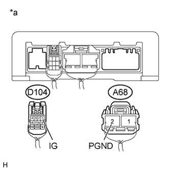
D104-1 (IG) - A68-2 (PGND)
| Ignition switch ON
| 11 to 14 V
|
Text in Illustration*a
| Rear view of wire harness connector
(to Power Steering ECU Assembly)
|
| | REPAIR OR REPLACE HARNESS OR CONNECTOR |
|
|
| 2.CHECK HARNESS AND CONNECTOR (POWER STEERING ECU ASSEMBLY - BODY GROUND) |
Disconnect the power steering ECU assembly connector.
Measure the voltage according to the value(s) in the table below.
- Standard Voltage:
Tester Connection
| Switch Condition
| Specified Condition
|
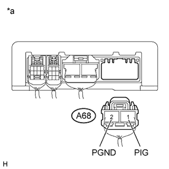
A68-1 (PIG) - Body ground
| Ignition switch ON
| 11 to 14 V
|
Measure the resistance according to the value(s) in the table below.
- Standard Resistance:
Tester Connection
| Condition
| Specified Condition
|
A68-2 (PGND) - Body ground
| Always
| Below 1 Ω
|
Text in Illustration*a
| Rear view of wire harness connector
(to Power Steering ECU Assembly)
|
| | REPAIR OR REPLACE HARNESS OR CONNECTOR |
|
|