Air Conditioning System (For Hatchback) Recirculation Damper Servo Motor Circuit
DESCRIPTION
WIRING DIAGRAM
INSPECTION PROCEDURE
INSPECT NO. 1 BLOWER DAMPER SERVO SUB-ASSEMBLY (AIR INLET SERVO MOTOR)
INSPECT NO. 1 HEATER CONTROL SUB-ASSEMBLY (FRESH/RECIRC SWITCH, MODE SWITCH)
CHECK HARNESS AND CONNECTOR (BLOWER DAMPER SERVO SUB-ASSEMBLY - IG1 NO. 1 RELAY)
CHECK HARNESS AND CONNECTOR (NO. 1 HEATER CONTROL SUB-ASSEMBLY - IG1 NO. 1 RELAY)
CHECK HARNESS AND CONNECTOR (NO. 1 HEATER CONTROL SUB-ASSEMBLY - BODY GROUND)
CHECK HARNESS AND CONNECTOR (NO. 1 HEATER CONTROL SUB-ASSEMBLY - BLOWER DAMPER SERVO SUB-ASSEMBLY)
CHECK HARNESS AND CONNECTOR (NO. 1 HEATER CONTROL SUB-ASSEMBLY - AIR CONDITIONING AMPLIFIER ASSEMBLY)
AIR CONDITIONING SYSTEM (for Hatchback) - Recirculation Damper Servo Motor Circuit |
DESCRIPTION
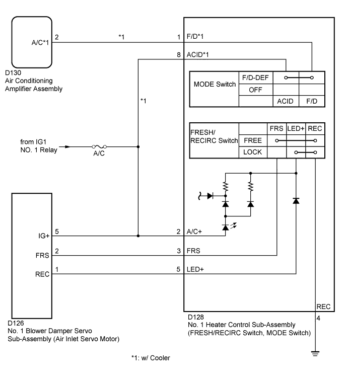
The No. 1 blower damper servo sub-assembly (air inlet servo motor) and No. 1 heater control sub-assembly (FRESH/RECIRC switch, MODE switch) are powered through the A/C fuse. Operating the No. 1 heater control sub-assembly (FRESH/RECIRC switch, MODE switch) drives the No. 1 blower damper servo sub-assembly (air inlet servo motor) to switch between "FRESH" and "RECIRCULATION".
WIRING DIAGRAM
INSPECTION PROCEDURE
- NOTICE:
- Inspect the fuses for circuits related to this system before performing the following inspection procedures.
| 1.INSPECT NO. 1 BLOWER DAMPER SERVO SUB-ASSEMBLY (AIR INLET SERVO MOTOR) |
Inspect the No. 1 blower damper servo sub-assembly (air inlet servo motor) (YARIS_NCP93 RM000003TQM00AX.html).
| 2.INSPECT NO. 1 HEATER CONTROL SUB-ASSEMBLY (FRESH/RECIRC SWITCH, MODE SWITCH) |
Inspect the No. 1 heater control sub-assembly (FRESH/RECIRC switch, MODE switch) (YARIS_NCP93 RM00000314R026X.html).
| 3.CHECK HARNESS AND CONNECTOR (BLOWER DAMPER SERVO SUB-ASSEMBLY - IG1 NO. 1 RELAY) |
Disconnect the D126 No. 1 blower damper servo sub-assembly (air inlet servo motor) connector.
Measure the voltage according to the value(s) in the table below.
- Standard Voltage:
Tester Connection
| Switch Condition
| Specified Condition
|
D126-5 (IG+) - Body ground
| Ignition switch off
| Below 1 V
|
D126-5 (IG+) - Body ground
| Ignition switch ON
| 11 to 14 V
|
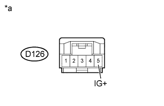
Text in Illustration*a
| Front view of wire harness connector
(to No. 1 Blower Damper Servo Sub-Assembly (Air Inlet Servo Motor))
|
| | REPAIR OR REPLACE HARNESS OR CONNECTOR |
|
|
| 4.CHECK HARNESS AND CONNECTOR (NO. 1 HEATER CONTROL SUB-ASSEMBLY - IG1 NO. 1 RELAY) |
Disconnect the D128 No. 1 heater control sub-assembly (FRESH/RECIRC switch, MODE switch) connector.
Measure the voltage according to the value(s) in the table below.
- Standard Voltage:
Tester Connection
| Switch Condition
| Specified Condition
|
D128-2 (A/C+) - Body ground
| Ignition switch off
| Below 1 V
|
D128-2 (A/C+) - Body ground
| Ignition switch ON
| 11 to 14 V
|
D128-8 (ACID) - Body ground*1
| Ignition switch off
| Below 1 V
|
D128-8 (ACID) - Body ground*1
| Ignition switch ON
| 11 to 14 V
|
*1: w/ Cooler
Text in Illustration*A
| w/ Cooler
|
*a
| Front view of wire harness connector
(to No. 1 Heater Control Sub-Assembly (FRESH/RECIRC Switch, MODE Switch))
|
| | REPAIR OR REPLACE HARNESS OR CONNECTOR |
|
|
| 5.CHECK HARNESS AND CONNECTOR (NO. 1 HEATER CONTROL SUB-ASSEMBLY - BODY GROUND) |
Disconnect the D128 No. 1 heater control sub-assembly (FRESH/RECIRC switch, MODE switch) connector.
Measure the resistance according to the value(s) in the table below.
- Standard Resistance:
Tester Connection
| Condition
| Specified Condition
|
D128-4 (REC) - Body ground
| Always
| Below 1 Ω
|
Text in Illustration*a
| Front view of wire harness connector
(to No. 1 Heater Control Sub-Assembly (FRESH/RECIRC Switch, MODE Switch))
|
| | REPAIR OR REPLACE HARNESS OR CONNECTOR |
|
|
| 6.CHECK HARNESS AND CONNECTOR (NO. 1 HEATER CONTROL SUB-ASSEMBLY - BLOWER DAMPER SERVO SUB-ASSEMBLY) |
Disconnect the D128 No. 1 heater control sub-assembly (FRESH/RECIRC switch, MODE switch) connector.
Disconnect the D126 No. 1 blower damper servo sub-assembly (air inlet servo motor) connector.
Measure the resistance according to the value(s) in the table below.
- Standard Resistance:
Tester Connection
| Condition
| Specified Condition
|
D128-3 (FRS) - D126-2 (FRS)
| Always
| Below 1 Ω
|
D128-5 (LED+) - D126-1 (REC)
| Always
| Below 1 Ω
|
D128-3 (FRS) - Body ground
| Always
| 10 kΩ or higher
|
D128-5 (LED+) - Body ground
| Always
| 10 kΩ or higher
|
ResultResult
| Proceed to
|
NG
| A
|
OK (w/ cooler)
| B
|
OK (w/o cooler)
| C
|
| A |
|
|
|
| REPAIR OR REPLACE HARNESS OR CONNECTOR |
|
| 7.CHECK HARNESS AND CONNECTOR (NO. 1 HEATER CONTROL SUB-ASSEMBLY - AIR CONDITIONING AMPLIFIER ASSEMBLY) |
Disconnect the D128 No. 1 heater control sub-assembly (FRESH/RECIRC switch, MODE switch) connector.
Disconnect the D130 air conditioning amplifier assembly connector.
Measure the resistance according to the value(s) in the table below.
- Standard Resistance:
Tester Connection
| Condition
| Specified Condition
|
D128-1 (F/D) - D130-2 (A/C)
| Always
| Below 1 Ω
|
D128-1 (F/D) - Body ground
| Always
| 10 kΩ or higher
|
| | REPAIR OR REPLACE HARNESS OR CONNECTOR |
|
|