Dtc B1500 Fuel Sender Open Detected
DESCRIPTION
WIRING DIAGRAM
INSPECTION PROCEDURE
PERFORM ACTIVE TEST USING TECHSTREAM (FUEL METER OPERATION)
READ VALUE USING TECHSTREAM (FUEL INPUT)
INSPECT FUEL SENDER GAUGE ASSEMBLY
INSPECT FUEL SUCTION WITH PUMP AND GAUGE TUBE ASSEMBLY
CHECK HARNESS AND CONNECTOR (COMBINATION METER ASSEMBLY - FUEL SUCTION WITH PUMP AND GAUGE TUBE ASSEMBLY)
DTC B1500 Fuel Sender Open Detected |
DESCRIPTION
This DTC is output when the combination meter assembly detects a fuel sender gauge malfunction.DTC No.
| DTC Detection Condition
| Trouble Area
|
B1500
| When combination meter detects fuel sender gauge malfunction
| - Harness or connector
- Combination meter assembly
- Fuel suction with pump and gauge assembly
- Fuel sender gauge assembly
|
WIRING DIAGRAM
INSPECTION PROCEDURE
| 1.PERFORM ACTIVE TEST USING TECHSTREAM (FUEL METER OPERATION) |
Connect the Techstream to the DLC3.
Turn the ignition switch to ON.
Turn the Techstream on.
Enter the following menus: Body Electrical / Combination Meter / Active Test.
According to the display on the Techstream, perform the Active Test.
Combination MeterTester Display
| Test part
| Control Range
| Diagnostic Note
|
Fuel Meter Operation
| Fuel gauge
| EMPTY / 1/2 / FULL
| Vehicle is stopped and the engine idling
|
- OK:
- Fuel receiver gauge indication is normal.
| 2.READ VALUE USING TECHSTREAM (FUEL INPUT) |
Connect the Techstream to the DLC3.
Turn the ignition switch to ON.
Turn the Techstream on.
Enter the following menus: Body Electrical / Combination Meter / Data List.
According to the display on the Techstream, read the Data List.
Combination MeterTester Display
| Measurement Item/Range
| Normal Condition
| Diagnostic Note
|
Fuel Input
| Fuel sender gauge input/
Min.: 0
Max.: 127.5
| Fuel sender input value
| Unit: Liter
|
- OK:
- Fuel value displayed on the tester is approximately the same as needle indication.
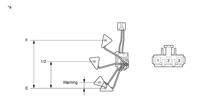
| 3.INSPECT FUEL SENDER GAUGE ASSEMBLY |
Remove the fuel sender gauge assembly (YARIS_NCP93 RM000000SL805GX.html).
Text in Illustration*a
| Component without harness connected
(Fuel Sender Gauge Assembly)
| -
| -
|
Check that the float moves smoothly between F and E.
Measure the resistance according to the value(s) in the table below.
- Standard Resistance:
Tester Connection
| Float Level
| Float Position (mm (in.))
| Specified Condition
|
1 - 2
| F
| 142 to 152 (5.591 to 5.984)
| 13.5 to 16.5 Ω
|
1/2
| 71.1 to 76.1 (2.799 to 2.996)
| 208.3 Ω
|
Warning
| 5.9 to 10.9 (0.232 to 0.429)
| 365.2 Ω
|
E
| 0 (0)
| 405.5 to 414.5 Ω
|
Reinstall the fuel sender gauge assembly.
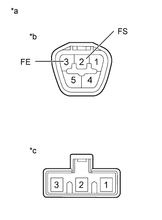
| 4.INSPECT FUEL SUCTION WITH PUMP AND GAUGE TUBE ASSEMBLY |
Remove the fuel suction with pump and gauge tube assembly (YARIS_NCP93 RM000004NLO00FX_01_0009.html).
Measure the resistance according to the value(s) in the table below.
- Standard Resistance:
Tester Connection
| Condition
| Specified Condition
|
A-2 (FS) - B-2
| Always
| Below 1 Ω
|
A-3 (FE) - B-1
| Always
| Below 1 Ω
|
Text in Illustration*a
| Component without harness connected
(Fuel Suction with Pump and Gauge Tube Assembly)
|
*b
| Connector A
|
*c
| Connector B
|
Reinstall the fuel suction plate sub-assembly.
| 5.CHECK HARNESS AND CONNECTOR (COMBINATION METER ASSEMBLY - FUEL SUCTION WITH PUMP AND GAUGE TUBE ASSEMBLY) |
Disconnect the D100 combination meter assembly connector.
Disconnect the J71 fuel suction with pump and gauge tube assembly connector.
Measure the resistance according to the value(s) in the table below.
- Standard Resistance:
Tester Connection
| Condition
| Specified Condition
|
D100-16 (L) - J71-2 (FS)
| Always
| Below 1 Ω
|
D100-16 (L) - Body ground
| Always
| 10 kΩ or higher
|
J71-3 (FE) - Body ground
| Always
| Below 1 Ω
|
Reconnect the fuel suction with pump and gauge tube assembly connector.
Reconnect the combination meter assembly connector.
| | REPAIR OR REPLACE HARNESS OR CONNECTOR |
|
|