INSTALL BACK DOOR OPENER SWITCH ASSEMBLY (w/ Power Door Lock)
INSTALL BACK DOOR OUTSIDE HANDLE SUB-ASSEMBLY (w/o Power Door Lock)
INSTALL BACK DOOR OUTSIDE GARNISH SUB-ASSEMBLY (w/ Power Door Lock)
INSTALL BACK DOOR OUTSIDE GARNISH SUB-ASSEMBLY (w/o Power Door Lock)
INSTALL BACK DOOR LOCK CONTROL ASSEMBLY (w/o Power Door Lock)
INSTALL BACK DOOR LOCK CYLINDER ASSEMBLY (w/ Power Door Lock)
INSTALL BACK DOOR LOCK CYLINDER ASSEMBLY (w/o Power Door Lock)
Back Door (For Hatchback) -- Reassembly |
| 1. APPLY BODY GREASE |
| 2. INSTALL NO. 2 LUGGAGE COMPARTMENT DOOR NAME PLATE |
Clean the attachment surface.
Using an infrared light, heat the double-sided tape remaining on the back door panel.
Heating Temperature Item Temperature Vehicle Body 40 to 60°C (104 to 140°F) - CAUTION:
- Do not burn yourself on the hot body panel or with the infrared light.
- NOTICE:
- Do not heat the vehicle body excessively.
Using a piece of cloth, rub the double-sided tape off the back door panel while it is hot from the infrared light.
- NOTICE:
- Installing the No. 2 luggage compartment door name plate while any double-sided tape remains on the back door panel may cause adhesion failure. Therefore, completely remove the double-sided tape.
Using a non-residue solvent, clean the attachment surface.
Install a new No. 2 luggage compartment door name plate as shown in the illustration.

- Installation Position:
Mark Measurement (along surface) *1 223.8 mm (8.81 in.) *2 211.9 mm (8.34 in.) *3 167.1 mm (6.58 in.)
- NOTICE:
- Install the No. 2 luggage compartment door name plate in an environment where the ambient temperature is over 20°C (68°F). If it is below 20°C (68°F), using an infrared light, heat the back door panel and the No. 2 luggage compartment door name plate to 20 to 30°C (68 to 86°F) and install the No. 2 luggage compartment door name plate.
| 3. INSTALL NO. 6 BACK DOOR NAME PLATE |
Clean the attachment surface.
Using an infrared light, heat the double-sided tape remaining on the back door panel.
Heating Temperature Item Temperature Vehicle Body 40 to 60°C (104 to 140°F) - CAUTION:
- Do not burn yourself on the hot body panel or with the infrared light.
- NOTICE:
- Do not heat the vehicle body excessively.
Using a piece of cloth, rub the double-sided tape off the back door panel while it is hot from the infrared light.
- NOTICE:
- Installing the No. 6 back door name plate while any double-sided tape remains on the back door panel may cause adhesion failure. Therefore, completely remove the double-sided tape.
Using a non-residue solvent, clean the attachment surface.
Install a new No. 6 back door name plate as shown in the illustration.

- Installation Position:
Mark Measurement (along surface) *1 215.8 mm (8.50 in.) *2 220.0 mm (8.66 in.) *3 51.5 mm (2.03 in.)
- NOTICE:
- Install the No. 6 back door name plate in an environment where the ambient temperature is over 20°C (68°F). If it is below 20°C (68°F), using an infrared light, heat the back door panel and the No. 6 back door name plate to 20 to 30°C (68 to 86°F) and install the No. 6 back door name plate.
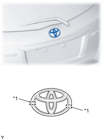
| 4. INSTALL SYMBOL EMBLEM |
Clean the attachment surface.
Using an infrared light, heat the double-sided tape remaining on the back door panel.
Heating Temperature Item Temperature Vehicle Body 40 to 60°C (104 to 140°F) - CAUTION:
- Do not burn yourself on the hot body panel or with the infrared light.
- NOTICE:
- Do not heat the vehicle body excessively.
Using a piece of cloth, rub the remaining double-sided tape off the back door panel while it is hot from the infrared light.
- NOTICE:
- Installing the symbol emblem with any double-sided tape remaining on the back door panel may cause adhesion failure. Therefore, completely remove the double-sided tape.
Using a non-residue solvent, clean the attachment surface.
Insert the 2 pins into the back door panel and install a new symbol emblem.
Text in Illustration *1 Location Pin - NOTICE:
- Install the symbol emblem in an environment where the ambient temperature is over 20 °C (68°F). If it is below 20°C (68°F), using an infrared light, heat the back door panel and the symbol emblem to 20 to 30°C (68 to 86°F) and install the symbol emblem.
 |
| 5. INSTALL PACKAGE TRAY TRIM HANGER |
- HINT:
- Use the same procedures for the opposite side.
Install the package tray trim hanger.
 |
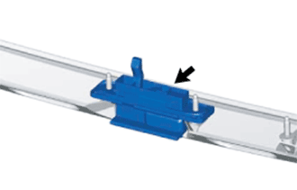
| 6. INSTALL BACK DOOR NO. 2 WIRE |
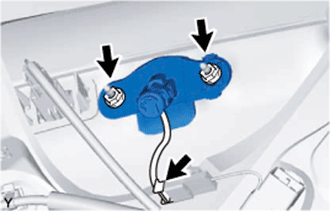
Engage the 4 clamps and connect the connector.
Text in Illustration *1 Hook *2 Clamp
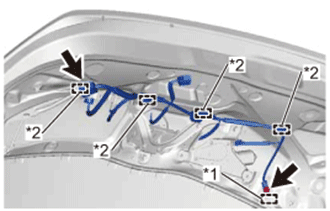 |
Engage the hook and install the wire harness with the bolt.
- Torque:
- 8.4 N*m{85 kgf*cm, 74 in.*lbf}
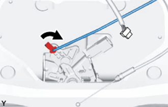
| 7. INSTALL REAR WINDOW NO. 1 WIRE (w/ Rear Window Defogger) |
Engage the hook and install the bolt.
Text in Illustration *1 Hook *2 Clamp - Torque:
- 8.4 N*m{85 kgf*cm, 74 in.*lbf}
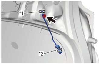 |
Engage the clamp and install the wire harness.
| 8. INSTALL LICENSE PLATE LIGHT ASSEMBLY |
Engage the 2 claws to install the license plate light assembly.
Connect the connector.
| 9. INSTALL BACK DOOR PANEL CUSHION |
- HINT:
- Use the same procedures for the opposite side.
Install the new back door panel cushion.
 |
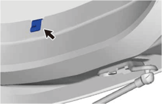
| 10. INSTALL BACK DOOR PANEL NO. 2 PROTECTOR |
Using a piece of cloth or similar material, rub off any double-sided tape remaining on the back door panel.
Text in Illustration *1 Double-sided Tape - NOTICE:
- Installing the back door panel protector with any double-sided tape remaining on the back door panel may cause adhesion failure. Therefore, completely remove the double-sided tape.
 |
Using a non-residue solvent, clean the attachment surface.
Remove the double-sided tape backing of the new back door panel protector.
Install the back door panel protector with 2 clips.
- NOTICE:
- Thoroughly press the back door panel protector to ensure that it adheres.
| 11. INSTALL BACK DOOR PANEL NO. 1 PROTECTOR |
- HINT:
- Use the same procedures as for the No. 2.
| 12. INSTALL REAR WASHER NOZZLE (w/ Rear Wiper) |
Connect the rear washer nozzle to the washer hose.
Engage the 2 claws and install the rear washer nozzle.
| 13. INSTALL CENTER STOP LIGHT ASSEMBLY |
Install a new packing.
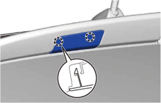
Engage the 4 claws to install a new clip.
Text in Illustration *a Upper Side (side with short claws) *b Lower Side (side with long claws) - NOTICE:
- Make sure not to install the clip upside-down.
- HINT:
- Use the same procedure as for the opposite side.
 |
Connect the connector.
Engage the 4 claws of the clips and install the center stop light assembly.
- NOTICE:
- Make sure not to deform the packing at this point.
 |
| 14. INSTALL REAR LIGHT COVER |
Engage the 6 claws and install the rear lamp cover.
 |
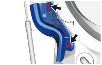
| 15. INSTALL BACK DOOR OPENER SWITCH ASSEMBLY (w/ Power Door Lock) |
Install the back door opener switch.
- HINT:
- Make sure the arrows on the back door opener switch and the back door garnish are pointing in the same direction.
| 16. INSTALL BACK DOOR OUTSIDE HANDLE SUB-ASSEMBLY (w/o Power Door Lock) |
Install the back door outside handle.
 |
| 17. INSTALL BACK DOOR OUTSIDE GARNISH SUB-ASSEMBLY (w/ Power Door Lock) |
Engage the 2 clips and install the back door outside garnish.
Tighten the 3 nuts.
- Torque:
- 4.9 N*m{50 kgf*cm, 43 in.*lbf}
Connect the connectors.
| 18. INSTALL BACK DOOR OUTSIDE GARNISH SUB-ASSEMBLY (w/o Power Door Lock) |
Engage the 2 clips and install the back door outside garnish.
Tighten the nut.
- Torque:
- 4.9 N*m{50 kgf*cm, 43 in.*lbf}
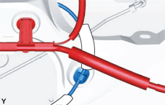
| 19. INSTALL BACK DOOR LOCK CONTROL ASSEMBLY (w/o Power Door Lock) |
Install the back door lock control with the 2 nuts.
- Torque:
- 4.9 N*m{50 kgf*cm, 43 in.*lbf}
Engage the clamp.
- NOTICE:
- Make sure to pass the cable behind the wire harness.
 |
| 20. INSTALL BACK DOOR GARNISH NO. 2 RETAINER (w/ Cover) |
Install the back door garnish No. 2 retainer with the 2 nuts.
- Torque:
- 4.9 N*m{50 kgf*cm, 43 in.*lbf}
 |
| 21. INSTALL BACK DOOR LOCK CYLINDER ASSEMBLY (w/ Power Door Lock) |
Engage the 2 claws and install the back door lock cylinder.
 |
Install the back door lock cylinder with the 2 nuts.
- Torque:
- 4.9 N*m{50 kgf*cm, 43 in.*lbf}
 |
Connect the connector.
| 22. INSTALL BACK DOOR LOCK CYLINDER ASSEMBLY (w/o Power Door Lock) |
Install the back door lock cylinder with the 2 nuts.
- Torque:
- 4.9 N*m{50 kgf*cm, 43 in.*lbf}
| 23. INSTALL BACK DOOR LOCK CONTROL ROD (w/o Power Door Lock) |
Install the back door lock control rod.
 |
| 24. INSTALL DOOR PULL HANDLE |
Engage the 4 claws and install the door pull handle.
 |
| 25. INSTALL BACK DOOR LOCK ASSEMBLY (w/ Power Door Lock) |
- HINT:
- Make sure to remove the string before installing a new back door lock assembly.
Apply MP grease to the sliding parts of the back door lock assembly.
Install the back door lock assembly with the 2 bolts.
- Torque:
- 7.5 N*m{76 kgf*cm, 66 in.*lbf}
Connect the connector.
| 26. INSTALL BACK DOOR LOCK ASSEMBLY (w/o Power Door Lock) |
Apply MP grease to the sliding parts of the back door lock assembly.
Install the back door lock assembly with the 2 bolts.
- Torque:
- 7.5 N*m{76 kgf*cm, 66 in.*lbf}
Connect the back door lock control rod.
 |
Connect the back door outside handle cable.
Connect the connector.
| 27. INSTALL REAR WIPER MOTOR GROMMET (w/ Rear Wiper) |
Apply MP grease to the entire surface of the rear wiper motor grommet lip.
- HINT:
- Make sure that the hole does not get clogged with MP grease and the grooves on the lip are filled with MP grease.
Text in Illustration 
Lip of Rear Wiper Motor Grommet
 |
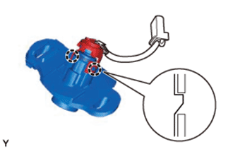
| 28. INSTALL REAR WIPER MOTOR ASSEMBLY (w/ Rear Wiper) |
Install the rear wiper motor with the 3 bolts in the order shown in the illustration.
- Torque:
- 5.5 N*m{56 kgf*cm, 49 in.*lbf}
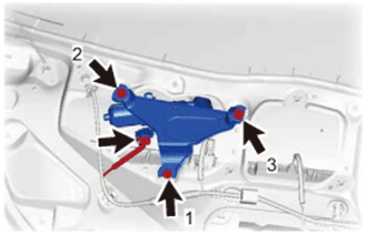 |
Connect the connector.
| 29. INSTALL REAR WIPER ARM AND BLADE ASSEMBLY (w/ Rear Wiper) |
Operate the wiper and stop the rear wiper motor at the automatic stop position.
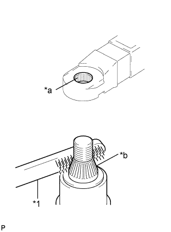 |
Scrape any metal powder off the serrated part of the wiper arm with a round file or the equivalent (when reinstalling).
Clean the wiper pivot serrations with a wire brush.
Text in Illustration *1 Wire Brush *a Wiper Arm Serration *b Wiper Pivot Serration
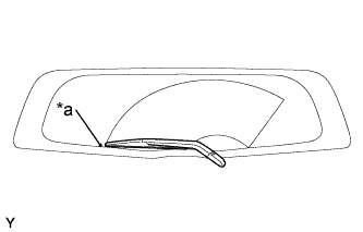
Install the rear wiper arm and blade with the nut to the position as shown in the illustration.
- Torque:
- 5.5 N*m{56 kgf*cm, 49 in.*lbf}
- HINT:
- Hold the arm hinge by hand while tightening the nut.
Text in Illustration *a Mark for Blade Position
 |
Operate the rear wiper while spraying washer fluid on the glass. Make sure that the rear wiper functions properly and there is no interference with the vehicle body.
| 30. INSTALL REAR WIPER ARM HEAD CAP (w/ Rear Wiper) |
Engage the 2 claws and 2 hinges, and install the rear wiper arm head cap.
- HINT:
- Push down on the cap until a click sound can be heard.
| 31. INSTALL BACK DOOR TRIM BOARD |
Engage the 11 clips and install the back door trim board.
 |
| 32. INSTALL REAR SPOILER SUB-ASSEMBLY (w/ Rear Spoiler) |
Clean the attachment surface.
Using an infrared light, heat the double-sided adhesive tape remaining on the back door panel.
Heating Temperature Item Temperature Vehicle Body 40 to 60°C (104 to 140°F) - CAUTION:
- Do not burn yourself on the hot back door panel or with the infrared light.
- NOTICE:
- Do not heat the back door panel excessively.
Using a piece of cloth, rub the remaining double-sided tape off the back door panel while it is hot from the infrared light.
- NOTICE:
- Installing the rear spoiler while any double-sided tape remains on the back door panel may cause adhesion failure. Therefore, completely remove the double-sided adhesive tape.
Using a non-residue solvent, clean the attachment surface.
Engage the 4 clips and install a new rear spoiler.
Tighten the 2 screws.
| 33. INSTALL REAR SPOILER COVER LH (w/ Rear Spoiler) |
Engage the 2 claws and install the rear spoiler cover.
 |
| 34. INSTALL REAR SPOILER COVER RH (w/ Rear Spoiler) |
- HINT:
- Use the same procedure as for the LH side.