Drivetrain. Yaris. Ncp93, 131
U340E Automatic Transmission Transaxle. Yaris. Ncp93, 131
Shift Lever (For Hatchback) -- Inspection |
| 1. INSPECT SHIFT LOCK CONTROL ECU |
Measure the voltage according to the value(s) in the table below.
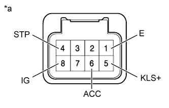
Text in Illustration *a Component with harness connected
(Shift Lock Control ECU)- NOTICE:
- Do not disconnect the shift lock control ECU connector.
- Standard Voltage:
Tester Connection Switch Condition Specified Condition 4 (STP) - 1 (E) Brake pedal depressed 11 to 14 V Brake pedal released Below 1 V 5 (KLS+) - 1 (E) 1. Ignition switch ACC and shift lever in P Below 1 V 2. Ignition switch ACC and shift lever not in P
(Within approx. 1 second)7.5 to 10.5 V 3. Ignition switch ACC and shift lever not in P
(After approx. 1 second)6 to 9 V 6 (ACC) - 1 (E) Ignition switch ACC 11 to 14 V Ignition switch ON 11 to 14 V Ignition switch off Below 1 V 8 (IG) - 1 (E) Ignition switch ON 11 to 14 V Ignition switch off Below 1 V
 |
Measure the resistance according to the value(s) in the table below.
- NOTICE:
- Do not disconnect the shift lock control ECU connector.
- Standard Resistance:
Tester Connection Condition Specified Condition 1 (E) - Body ground When battery voltage not applied Below 1 Ω
| 2. INSPECT TRANSMISSION CONTROL SWITCH |
Measure the resistance according to the value(s) in the table below when the shift lever is moved to each position.
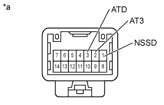
Text in Illustration *a Component without harness connected
(Transmission Control Switch)- Standard Resistance:
Tester Connection Shift Position Specified Condition 1 (NSSD) - 2 (AT3) 3 and 2 Below 1 Ω Except 3 and 2 10 kΩ or higher 1 (NSSD) - 3 (ATD) Except 3 and 2 Below 1 Ω 3 and 2 10 kΩ or higher
 |
| 3. INSPECT SHIFT LOCK SOLENOID |
Disconnect the shift lock solenoid connector.
Measure the resistance according to the value(s) in the table below when the shift lever is moved to each position.
Text in Illustration *a Component without harness connected
(Shift Lock Solenoid)- Standard Resistance:
Tester Connection Shift Position Specified Condition 4 (P) - 3 (E2) P 10 kΩ or higher Except P Below 1 Ω
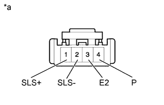 |
Measure the resistance according to the value(s) in the table below.
- Standard Resistance:
Tester Connection Condition Specified Condition 1 (SLS+) - 2 (SLS-) When battery voltage not applied 112 Ω