Can Communication System (For Hatchback Except Separate Type Yaw Rate Sensor) -- Terminals Of Ecu |
- HINT:
- Operating the ignition switch, any switches or any doors triggers related ECU and sensor communication with the CAN, which causes resistance variation.
| DISCONNECT CABLE FROM NEGATIVE BATTERY TERMINAL |
Disconnect the cable from the negative (-) battery terminal before measuring the resistances of the main wire and branch wire.
- CAUTION:
- Wait at least 90 seconds after disconnecting the cable from the negative (-) battery terminal to disable the SRS system.
- NOTICE:
- Before measuring the resistance, leave the vehicle for at least 1 minute and do not operate the ignition switch, any switches or any doors. If doors need to be opened in order to check connectors, open the doors and leave them open.
- When disconnecting the cable, some systems need to be initialized after the cable is reconnected (YARIS_NCP93 RM00000482M008X.html).
| JUNCTION CONNECTOR |
NO. 1 JUNCTION CONNECTOR

Text in Illustration *a to ECM *b to Skid Control ECU (Brake Actuator Assembly) (w/ ABS) *c to Main Body ECU (Multiplex Network Body ECU) *d to Power Steering ECU Assembly *e to DLC3 *f to No. 2 Junction Connector Terminal No. (Symbol) Wiring Color Connect to A73-9 (CANH) L ECM A73-20 (CANL) W A73-10 (CANH) G Skid Control ECU (Brake Actuator Assembly)*1 A73-21 (CANL) W D146-1 (CANH) R Main Body ECU (Multiplex Network Body ECU) D146-12 (CANL) W D146-2 (CANH) LG Power Steering ECU Assembly D146-13 (CANL) W D146-3 (CANH) GR DLC3 D146-14 (CANL) W D146-4 (CANH) SB No. 2 Junction Connector D146-15 (CANL) W - *1: w/ ABS
- *1: w/ ABS
NO. 2 JUNCTION CONNECTOR
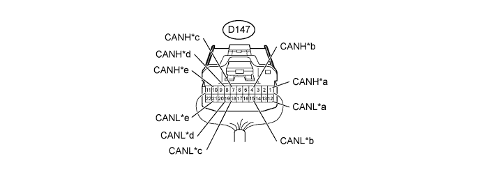
Text in Illustration *a to Steering Angle Sensor (Spiral Cable Sub-assembly)*1 *b to Airbag Sensor Assembly *c to Combination Meter Assembly *d to Air Conditioning Amplifier Assembly *e to No. 1 Junction Connector - - Terminal No. (Symbol) Wiring Color Connect to D147-1 (CANH) P Steering Angle Sensor (Spiral Cable Sub-assembly)*1 D147-12 (CANL) W D147-4 (CANH) B Airbag Sensor Assembly D147-15 (CANL) W D147-7 (CANH) G Combination Meter Assembly D147-18 (CANL) W D147-8 (CANH) V Air Conditioning Amplifier Assembly D147-19 (CANL) W D147-10 (CANH) SB No. 1 Junction Connector D147-21 (CANL) W - *1: w/ VSC
- *1: w/ VSC
| CHECK DLC3 |
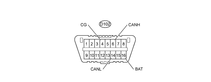
Turn the ignition switch off.
Measure the resistance according to the value(s) in the table below.
Terminal No. (Symbol) Wiring Color Switch Condition Specified Condition D102-6 (CANH) - D102-14 (CANL) GR - W Ignition switch off 54 to 69 Ω D102-6 (CANH) - D102-16 (BAT) GR - BE Ignition switch off 6 kΩ or higher D102-14 (CANL) - D102-16 (BAT) W - BE Ignition switch off 6 kΩ or higher D102-6 (CANH) - D102-4 (CG) GR - W-B Ignition switch off 200 Ω or higher D102-14 (CANL) - D102-4 (CG) W - W-B Ignition switch off 200 Ω or higher
| CHECK ECM |

Disconnect the A72 and C51 ECM connectors.
Measure the resistance according to the value(s) in the table below.
Terminal No. (Symbol) Wiring Color Switch Condition Specified Condition A72-13 (CANH) - A72-26 (CANL) L - W Ignition switch off 108 to 132 Ω A72-13 (CANH) - A72-2 (+B) L - B Ignition switch off 6 kΩ or higher A72-26 (CANL) - A72-2 (+B) W - B Ignition switch off 6 kΩ or higher A72-13 (CANH) - C51-16 (E1) L - W-B Ignition switch off 200 Ω or higher A72-26 (CANL) - C51-16 (E1) W - W-B Ignition switch off 200 Ω or higher
| CHECK MAIN BODY ECU (MULTIPLEX NETWORK BODY ECU), INSTRUMENT PANEL JUNCTION BLOCK ASSEMBLY (2 Connector Type) |
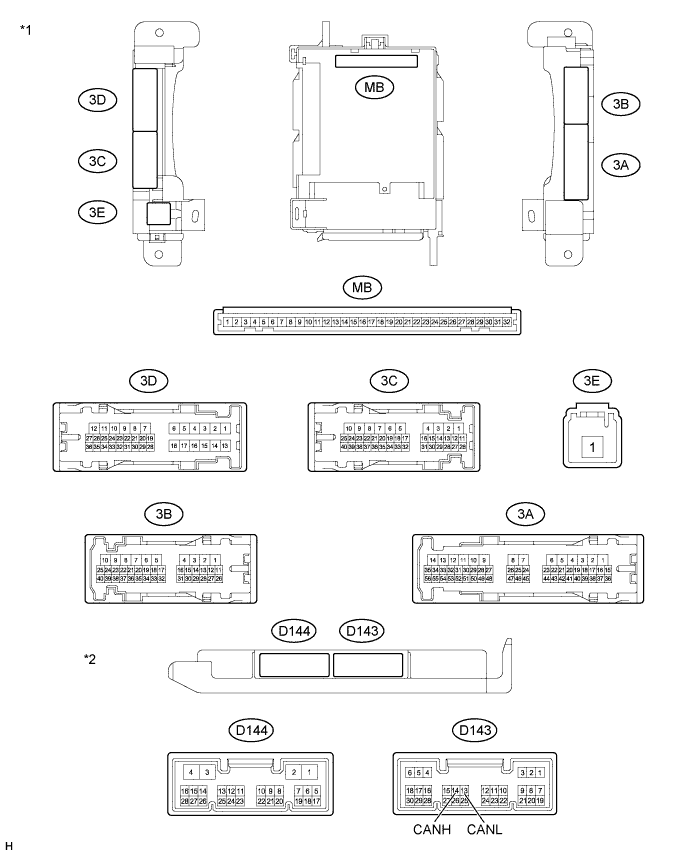
| *1 | Instrument Panel Junction Block Assembly | *2 | Main Body ECU (Multiplex Network Body ECU) |
Disconnect the D143 main body ECU (multiplex network body ECU) connector.
Disconnect the 3B and 3C instrument panel junction block assembly connectors.
Measure the resistance according to the value(s) in the table below.
Terminal No. (Symbol) Wiring Color Switch Condition Specified Condition D143-14 (CANH) - D143-13 (CANL) R - W Ignition switch off 54 to 69 Ω D143-14 (CANH) - 3C-21 R - L Ignition switch off 6 kΩ or higher D143-13 (CANL) - 3C-21 W - L Ignition switch off 6 kΩ or higher D143-14 (CANH) - 3B-8 R - W-B Ignition switch off 200 Ω or higher D143-13 (CANL) - 3B-8 W - W-B Ignition switch off 200 Ω or higher
| CHECK MAIN BODY ECU (MULTIPLEX NETWORK BODY ECU), INSTRUMENT PANEL JUNCTION BLOCK ASSEMBLY (1 Connector Type) |

| *1 | Instrument Panel Junction Block Assembly | *2 | Main Body ECU (Multiplex Network Body ECU) |
Disconnect the D143 main body ECU (multiplex network body ECU) connector.
Disconnect the 3B and 3C instrument panel junction block assembly connectors.
Measure the resistance according to the value(s) in the table below.
Terminal No. (Symbol) Wiring Color Switch Condition Specified Condition D143-14 (CANH) - D143-13 (CANL) R - W Ignition switch off 54 to 69 Ω D143-14 (CANH) - 3C-21 R - L Ignition switch off 6 kΩ or higher D143-13 (CANL) - 3C-21 W - L Ignition switch off 6 kΩ or higher D143-14 (CANH) - 3B-8 R - W-B Ignition switch off 200 Ω or higher D143-13 (CANL) - 3B-8 W - W-B Ignition switch off 200 Ω or higher
| CHECK COMBINATION METER ASSEMBLY |
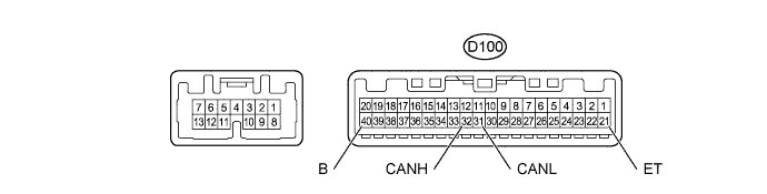
Disconnect the D100 combination meter assembly connector.
Measure the resistance according to the value(s) in the table below.
Terminal No. (Symbol) Wiring Color Switch Condition Specified Condition D100-32 (CANH) - D100-31 (CANL) G - W Ignition switch off 108 to 132 Ω D100-32 (CANH) - D100-40 (B) G - L Ignition switch off 6 kΩ or higher D100-31 (CANL) - D100-40 (B) W - L Ignition switch off 6 kΩ or higher D100-32 (CANH) - D100-21 (ET) G - W-B Ignition switch off 200 Ω or higher D100-31 (CANL) - D100-21 (ET) W - W-B Ignition switch off 200 Ω or higher
| CHECK SKID CONTROL ECU (BRAKE ACTUATOR ASSEMBLY) (w/ ABS) |
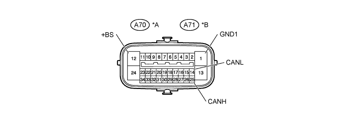
| *A | w/ VSC | *B | w/o VSC |
Disconnect the A70*1 or A71*2 skid control ECU (brake actuator assembly) connector.
Measure the resistance according to the value(s) in the table below.
*1: w/ VSCTerminal No. (Symbol) Wiring Color Switch Condition Specified Condition A70-25 (CANH) - A70-14 (CANL)*1
A71-25 (CANH) - A71-14 (CANL)*2G - W Ignition switch off 54 to 69 Ω A70-25 (CANH) - A70-12 (+BS)*1
A71-25 (CANH) - A71-12 (+BS)*2G - W Ignition switch off 6 kΩ or higher A70-14 (CANL) - A70-12 (+BS)*1
A71-14 (CANL) - A71-12 (+BS)*2W - W Ignition switch off 6 kΩ or higher A70-25 (CANH) - A70-1 (GND1)*1
A71-25 (CANH) - A71-1 (GND1)*2G - W-B Ignition switch off 200 Ω or higher A70-14 (CANL) - A70-1 (GND1)*1
A71-14 (CANL) - A71-1 (GND1)*2W - W-B Ignition switch off 200 Ω or higher
*2: w/o VSC
| CHECK AIRBAG SENSOR ASSEMBLY |
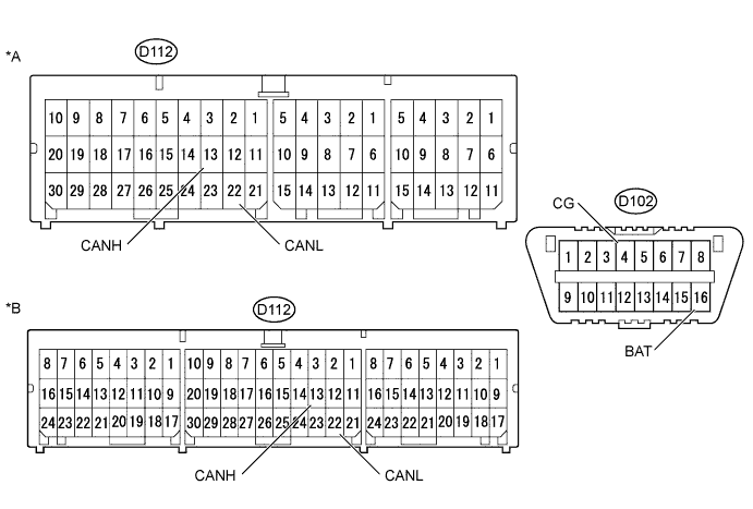
| *A | w/o VSC | *B | w/ VSC |
Disconnect the D112 airbag sensor assembly connector.
Measure the resistance according to the value(s) in the table below.
Terminal No. (Symbol) Wiring Color Switch Condition Specified Condition D112-13 (CANH) - D112-22 (CANL) B - W Ignition switch off 54 to 69 Ω D112-13 (CANH) - D102-16 (BAT) B - BE Ignition switch off 6 kΩ or higher D112-22 (CANL) - D102-16 (BAT) W - BE Ignition switch off 6 kΩ or higher D112-13 (CANH) - D102-4 (CG) B - W-B Ignition switch off 200 Ω or higher D112-22 (CANL) - D102-4 (CG) W - W-B Ignition switch off 200 Ω or higher
| CHECK STEERING ANGLE SENSOR (SPIRAL CABLE SUB-ASSEMBLY) (w/ VSC) |
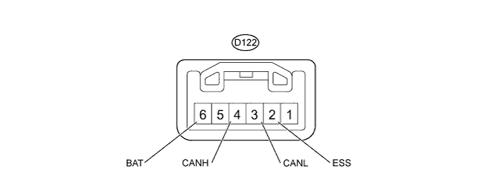
Disconnect the D122 steering angle sensor (spiral cable sub-assembly) connector.
Measure the resistance according to the value(s) in the table below.
Terminal No. (Symbol) Wiring Color Switch Condition Specified Condition D122-4 (CANH) - D122-3 (CANL) P - W Ignition switch off 54 to 69 Ω D122-4 (CANH) - D122-6 (BAT) P - SB Ignition switch off 6 kΩ or higher D122-3 (CANL) - D122-6 (BAT) W - SB Ignition switch off 6 kΩ or higher D122-4 (CANH) - D122-2 (ESS) P - BR Ignition switch off 200 Ω or higher D122-3 (CANL) - D122-2 (ESS) W - BR Ignition switch off 200 Ω or higher
| CHECK POWER STEERING ECU ASSEMBLY |
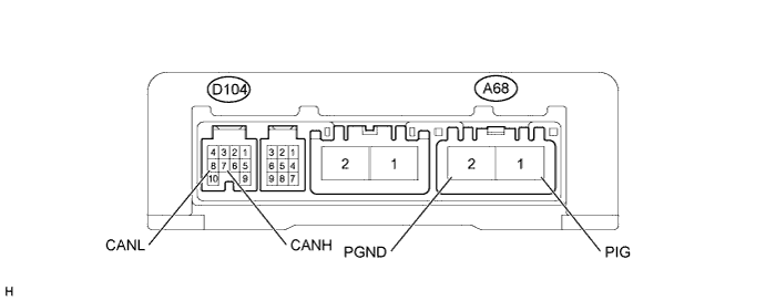
Disconnect the A68 and D104 power steering ECU assembly connectors.
Measure the resistance according to the value(s) in the table below.
Terminal No. (Symbol) Wiring Color Switch Condition Specified Condition D104-7 (CANH) - D104-8 (CANL) LG - W Ignition switch off 54 to 69 Ω D104-7 (CANH) - A68-1 (PIG) LG - W Ignition switch off 6 kΩ or higher D104-8 (CANL) - A68-1 (PIG) W - W Ignition switch off 6 kΩ or higher D104-7 (CANH) - A68-2 (PGND) LG - W-B Ignition switch off 200 Ω or higher D104-8 (CANL) - A68-2 (PGND) W - W-B Ignition switch off 200 Ω or higher
| CHECK AIR CONDITIONING AMPLIFIER ASSEMBLY |
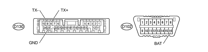
Disconnect the D130 air conditioning amplifier assembly connector.
Measure the resistance according to the value(s) in the table below.
Terminal No. (Symbol) Wiring Color Switch Condition Specified Condition D130-8 (TX+) - D130-9 (TX-) V - W Ignition switch off 54 to 69 Ω D130-8 (TX+) - D102-16 (BAT) V - BE Ignition switch off 6 kΩ or higher D130-9 (TX-) - D102-16 (BAT) W - BE Ignition switch off 6 kΩ or higher D130-8 (TX+) - D130-23 (GND) V - W-B Ignition switch off 200 Ω or higher D130-9 (TX-) - D130-23 (GND) W - W-B Ignition switch off 200 Ω or higher