Lighting System (For Sedan) Drl Relay Circuit
DESCRIPTION
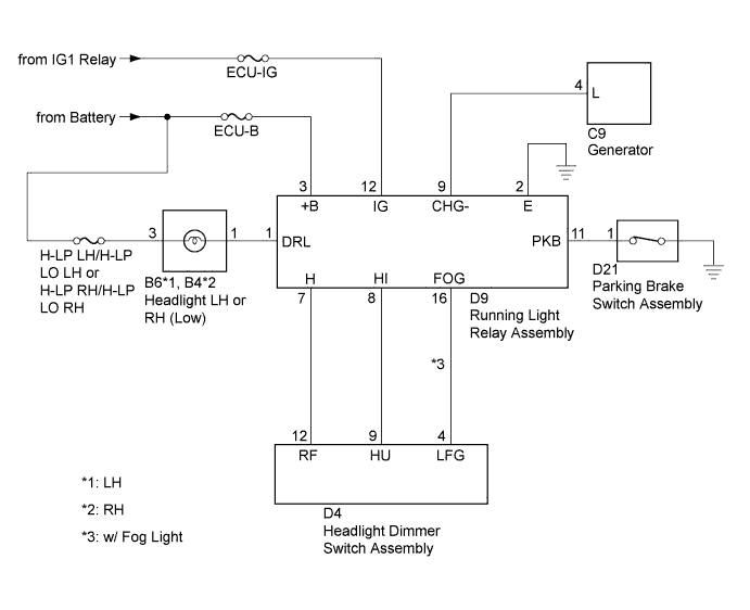
WIRING DIAGRAM
INSPECTION PROCEDURE
CHECK HARNESS AND CONNECTOR (RUNNING LIGHT RELAY ASSEMBLY - BATTERY, IG1 RELAY AND BODY GROUND)
CHECK HARNESS AND CONNECTOR (HEADLIGHT - RUNNING LIGHT RELAY ASSEMBLY)
CHECK HARNESS AND CONNECTOR (HEADLIGHT DIMMER SWITCH ASSEMBLY - RUNNING LIGHT RELAY ASSEMBLY)
CHECK HARNESS AND CONNECTOR (GENERATOR - RUNNING LIGHT RELAY ASSEMBLY)
CHECK HARNESS AND CONNECTOR (PARKING BRAKE SWITCH ASSEMBLY - RUNNING LIGHT RELAY ASSEMBLY)
LIGHTING SYSTEM (for Sedan) - DRL Relay Circuit |
DESCRIPTION
When the engine is started, signals are transmitted from the generator to the running light relay assembly, causing the headlights to illuminate.
WIRING DIAGRAM
INSPECTION PROCEDURE
- NOTICE:
- Inspect the fuses for circuits related to this system before performing the following inspection procedure.
| 1.CHECK HARNESS AND CONNECTOR (RUNNING LIGHT RELAY ASSEMBLY - BATTERY, IG1 RELAY AND BODY GROUND) |
Disconnect the D9 running light relay assembly connector.
Measure the voltage according to the value(s) in the table below.
- Standard Voltage:
Tester Connection
| Switch Condition
| Specified Condition
|
D9-3 (+B) - Body ground
| Always
| 11 to 14 V
|
D9-12 (IG) - Body ground
| Ignition switch ON
| 11 to 14 V
|
Measure the resistance according to the value(s) in the table below.
- Standard Resistance:
Tester Connection
| Condition
| Specified Condition
|
D9-2 (E) - Body ground
| Always
| Below 1 Ω
|
Text in Illustration*a
| Front view of wire harness connector
(to Running Light Relay Assembly)
|
| | REPAIR OR REPLACE HARNESS OR CONNECTOR |
|
|
| 2.CHECK HARNESS AND CONNECTOR (HEADLIGHT - RUNNING LIGHT RELAY ASSEMBLY) |
Disconnect the B6 or B4 headlight connector.
Disconnect the D9 running light relay assembly connector.
Measure the resistance according to the value(s) in the table below.
- Standard Resistance:
Tester Connection
| Condition
| Specified Condition
|
B6-1 or B4-1 - D9-1
| Always
| Below 1 Ω
|
B6-1 or B4-1 - Body ground
| Always
| 10 kΩ or higher
|
| | REPAIR OR REPLACE HARNESS OR CONNECTOR |
|
|
| 3.CHECK HARNESS AND CONNECTOR (HEADLIGHT DIMMER SWITCH ASSEMBLY - RUNNING LIGHT RELAY ASSEMBLY) |
Disconnect the D4 headlight dimmer switch assembly connector.
Disconnect the D9 running light relay assembly connector.
Measure the resistance according to the value(s) in the table below.
- Standard Resistance:
Tester Connection
| Condition
| Specified Condition
|
D4-12 (RF) - D9-7 (H)
| Always
| Below 1 Ω
|
D4-9 (HU) - D9-8 (HI)
| Always
| Below 1 Ω
|
D4-4 (LFG) - D9-16 (FOG)*1
| Always
| Below 1 Ω
|
D4-12 (RF) - Body ground
| Always
| 10 kΩ or higher
|
D4-9 (HU) - Body ground
| Always
| 10 kΩ or higher
|
D4-4 (LFG) - Body ground*1
| Always
| 10 kΩ or higher
|
*1: w/ Fog Light
| | REPAIR OR REPLACE HARNESS OR CONNECTOR |
|
|
| 4.CHECK HARNESS AND CONNECTOR (GENERATOR - RUNNING LIGHT RELAY ASSEMBLY) |
Disconnect the C9 generator connector.
Disconnect the D9 running light relay assembly connector.
Measure the resistance according to the value(s) in the table below.
- Standard Resistance:
Tester Connection
| Condition
| Specified Condition
|
C9-4 (L) - D9-9 (CHG-)
| Always
| Below 1 Ω
|
C9-4 (L) - Body ground
| Always
| 10 kΩ or higher
|
| | REPAIR OR REPLACE HARNESS OR CONNECTOR |
|
|
| 5.CHECK HARNESS AND CONNECTOR (PARKING BRAKE SWITCH ASSEMBLY - RUNNING LIGHT RELAY ASSEMBLY) |
Disconnect the D21 parking brake switch assembly connector.
Disconnect the D9 running light relay assembly connector.
Measure the resistance according to the value(s) in the table below.
- Standard Resistance:
Tester Connection
| Condition
| Specified Condition
|
D21-1 - D9-11 (PKB)
| Always
| Below 1 Ω
|
D21-1 - Body ground
| Always
| 10 kΩ or higher
|
| | REPAIR OR REPLACE HARNESS OR CONNECTOR |
|
|
| OK |
|
|
|
| REPLACE RUNNING LIGHT RELAY ASSEMBLY |
|