Vehicle Stability Control System (For Hatchback With Separate Type Yaw Rate Sensor) Terminals Of Ecu
TERMINALS OF ECU
TERMINAL INSPECTION
Vehicle Stability Control System (For Hatchback With Separate Type Yaw Rate Sensor) -- Terminals Of Ecu |
Text in Illustration*a
| Component without harness connected
(Skid Control ECU (Brake Actuator Assembly))
|
Terminal No. (Symbol)
| Terminal Description
|
A70-1 (GND1)
| Skid control ECU ground
|
A70-2 (STP)
| Stop light switch input
|
A70-4 (RL-)
| Rear wheel speed LH (-) signal input
|
A70-5 (RL+)
| Rear wheel speed LH (+) power supply output
|
A70-6 (FR-)
| Front wheel speed RH (-) signal input
|
A70-7 (FR+)
| Front wheel speed RH (+) power supply output
|
A70-11 (SP1)
| Speed signal output for speedometer
|
A70-12 (+BS)
| Solenoid relay power supply
|
A70-13 (GND2)
| Pump motor ground
|
A70-14 (CANL)
| CAN communication line L
|
A70-16 (RR-)
| Rear wheel speed RH (-) signal input
|
A70-17 (RR+)
| Rear wheel speed RH (+) power supply output
|
A70-18 (FL-)
| Front wheel speed LH (-) signal input
|
A70-19 (FL+)
| Front wheel speed LH (+) power supply output
|
A70-24 (BM)
| Motor relay power supply
|
A70-25 (CANH)
| CAN communication line H
|
A70-30 (CSW)
| VSC OFF switch input
|
A70-34 (IG1)
| ECU power supply
|

|
Disconnect the connector and measure the voltage or resistance on the wire harness side.
- HINT:
- Voltage cannot be measured with the connector connected to the brake actuator assembly (skid control ECU) as the connector is watertight.
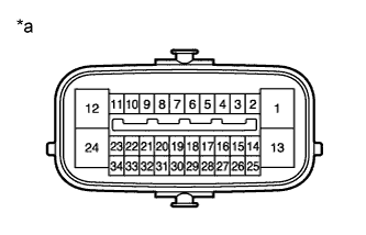
Text in Illustration*a
| Front view of wire harness connector
(to Skid Control ECU (Brake Actuator Assembly))
|
Standard:Terminal No. (Symbol)
| Wiring Color
| Terminal Description
| Condition
| Specified Condition
|
A70-1 (GND1) - Body ground
| W-B - Body ground
| Skid control ECU ground
| Always
| Below 1 Ω
|
A70-2 (STP) - Body ground
| P - Body ground
| Stop light switch input
| Stop light switch on → off
(Brake pedal depressed → released)
| 7.5 to 14 V
→ Below 1.5 V
|
A70-12 (+BS) - Body ground
| W - Body ground
| Solenoid relay power supply
| Always
| 11 to 14 V
|
A70-13 (GND2) - Body ground
| W-B - Body ground
| Pump motor ground
| Always
| Below 1 Ω
|
A70-24 (BM) - Body ground
| B - Body ground
| Motor relay power supply
| Always
| 11 to 14 V
|
A70-25 (CANH) - A70-14 (CANL)
| G - W
| CAN bus
| Ignition switch off
| 54 to 69 Ω
|
A70-30 (CSW) - Body ground
| B - Body ground
| VSC OFF switch input
| VSC OFF switch held on → off (Not pressed)
| Below 25 Ω → 10 kΩ or higher
|
A70-34 (IG1) - Body ground
| L - Body ground
| ECU power supply
| Ignition switch ON
| 11 to 14 V
|