Front Axle Hub (For Hatchback) Installation
INSTALL FRONT AXLE HUB BEARING
INSTALL FRONT AXLE HUB SUB-ASSEMBLY
INSTALL FRONT AXLE HUB HOLE SNAP RING
INSTALL FRONT AXLE ASSEMBLY
INSTALL FRONT LOWER SUSPENSION ARM
INSTALL TIE ROD END SUB-ASSEMBLY
INSTALL FRONT STABILIZER LINK ASSEMBLY
INSTALL FRONT SPEED SENSOR (w/ ABS)
INSPECT FRONT AXLE HUB BEARING BACKLASH
INSPECT FRONT AXLE HUB RUNOUT
INSTALL FRONT DISC
INSTALL FRONT DISC BRAKE CALIPER ASSEMBLY
INSTALL FRONT AXLE SHAFT NUT
INSTALL FRONT WHEEL
INSPECT AND ADJUST FRONT WHEEL ALIGNMENT
CHECK SPEED SENSOR SIGNAL (w/ ABS)
CHECK SPEED SENSOR SIGNAL (w/ VSC)
Front Axle Hub (For Hatchback) -- Installation |
- HINT:
- Use the same procedure for the RH side as for the LH side.
- The procedure listed below is for the LH side.
| 1. INSTALL FRONT AXLE HUB BEARING |
(YARIS_NCP93 RM000001IWO01LX.html)
| 2. INSTALL FRONT AXLE HUB SUB-ASSEMBLY |
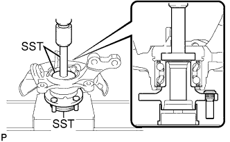
Using SST and a press, press the axle hub into the steering knuckle.
- SST
- 09950-70010(09951-07100)
09950-60010(09951-00580)
09608-32010
| 3. INSTALL FRONT AXLE HUB HOLE SNAP RING |
Using snap ring pliers, install a new axle hub hole snap ring, as shown in the illustration.
Text in Illustration*1
| Snap Ring Pliers
|
*a
| Speed Sensor Installation Gap
|
- NOTICE:
- Do not overlap the end of the snap ring and the installation hole in the speed sensor on the knuckle side.
- Do not damage the magnetic rotor surface of the bearing when installing the snap ring.
| 4. INSTALL FRONT AXLE ASSEMBLY |
Align the drive shaft splines and install the axle assembly.
- NOTICE:
- Do not damage the lower ball joint.
- Do not damage the threads of the drive shaft.
- Do not damage the speed sensor rotor.
- Do not damage the drive shaft outboard joint boot.
Install the front axle assembly onto the shock absorber with the 2 bolts and 2 nuts.
- Torque:
- 164 N*m{1672 kgf*cm, 121 ft.*lbf}
- HINT:
- Keep the bolt from rotating while turning the nut.
| 5. INSTALL FRONT LOWER SUSPENSION ARM |
Install the lower arm onto the steering knuckle with a new castle nut.
- Torque:
- 98 N*m{999 kgf*cm, 72 ft.*lbf}
- NOTICE:
- If the holes for the clip are not aligned, tighten the nut by a further turn of up to 60°.
Install a new clip.
| 6. INSTALL TIE ROD END SUB-ASSEMBLY |
Install the tie rod end sub-assembly onto the steering knuckle with a new castle nut.
- Torque:
- 49 N*m{500 kgf*cm, 36 ft.*lbf}
- NOTICE:
- If the holes for the clip are not aligned, tighten the nut by a further turn of up to 60°.
Install a new cotter pin.
| 7. INSTALL FRONT STABILIZER LINK ASSEMBLY |
Install the front stabilizer link assembly with the nut.
- Torque:
- 74 N*m{755 kgf*cm, 55 ft.*lbf}
- HINT:
- Using a socket hexagon wrench 6 to hold the stud.
| 8. INSTALL FRONT SPEED SENSOR (w/ ABS) |
Install the speed sensor onto the steering knuckle with the bolt.
- Torque:
- 8.5 N*m{87 kgf*cm, 75 in.*lbf}
- NOTICE:
- Check that the speed sensor tip and installation portion are free of foreign matter.
- Install the speed sensor without turning it from its original installation angle.
Install the flexible hose and speed sensor with the bolt.
- Torque:
- 29 N*m{300 kgf*cm, 22 ft.*lbf}
- NOTICE:
- Install the flexible hose and speed sensor without twisting them.
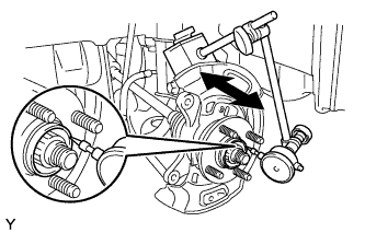
| 9. INSPECT FRONT AXLE HUB BEARING BACKLASH |
Using a dial indicator, check the backlash near the center of the axle hub.
- Maximum:
- 0.05 mm (0.00197 in.)
If the backlash exceeds the maximum, replace the front axle hub bearing.
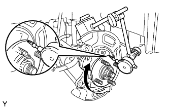
| 10. INSPECT FRONT AXLE HUB RUNOUT |
Using a dial indicator, check the runout of the surface of the axle hub.
- Maximum:
- 0.05 mm (0.00197 in.)
If the runout exceeds the maximum, replace the front axle hub sub-assembly and front axle hub bearing.
Align the matchmarks of the disc and axle hub and install the disc.
Text in Illustration*a
| Matchmark
|
- HINT:
- When replacing the disc, select the position that gives the minimum disc runout.
| 12. INSTALL FRONT DISC BRAKE CALIPER ASSEMBLY |
Install the disc brake caliper onto the steering knuckle.
- Torque:
- 107 N*m{1089 kgf*cm, 79 ft.*lbf}
| 13. INSTALL FRONT AXLE SHAFT NUT |
Clean the threaded parts on the front drive shaft and axle shaft nut using a non-residue solvent.
- NOTICE:
- Be sure to perform this work for a new front drive shaft.
- Keep the threaded parts free of oil and foreign objects.
Using a deep socket wrench 30 mm, install a new front axle shaft nut.
- Torque:
- 216 N*m{2203 kgf*cm, 159 ft.*lbf}
Using a chisel and hammer, stake the axle shaft nut.
- Torque:
- 103 N*m{1050 kgf*cm, 76 ft.*lbf}
| 15. INSPECT AND ADJUST FRONT WHEEL ALIGNMENT |
(YARIS_NCP93 RM000001BCN01XX.html)
| 16. CHECK SPEED SENSOR SIGNAL (w/ ABS) |
(YARIS_NCP93 RM000000XHT097X.html)
| 17. CHECK SPEED SENSOR SIGNAL (w/ VSC) |
(YARIS_NCP93 RM000000XHT098X.html)