Front Drive Shaft Assembly (For Sedan) -- Reassembly |
| 1. INSTALL FRONT DRIVE SHAFT DUST COVER |
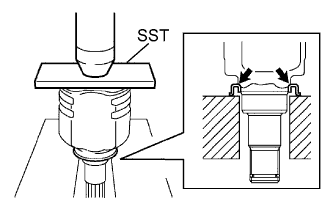 |
Using SST and a press, install a new dust cover into the inboard joint until it is flush with the end.
- SST
- 09527-10011
- NOTICE:
- Install the dust cover in the correct orientation.
- Do not deform the dust cover.
| 2. INSTALL FRONT DRIVE SHAFT HOLE SNAP RING |
Install a new snap ring.
| 3. INSTALL FRONT AXLE OUTBOARD JOINT BOOT |
Wrap the spline of the outboard joint shaft with protective tape.
Install new parts onto the outboard joint shaft in the following order.
1. Front axle outboard joint boot No. 2 clamp 2. Front axle outboard joint boot 3. Front axle outboard joint boot clamp
Pack the outboard joint shaft joint portion and outboard joint boot with grease.
- Standard Quantity:
- 125 to 135 g (4.4 to 4.8 oz.)
Install the outboard joint boot onto the outboard joint shaft groove.
- NOTICE:
- Keep the groove free of grease.
| 4. INSTALL FRONT NO. 2 AXLE OUTBOARD JOINT BOOT CLAMP |
- CAUTION:
- Wear protective gloves to avoid injuries to your hands.
Install the boot clamp onto the outboard joint boot and provisionally bend the lever.
- NOTICE:
- Set the lever into the guide groove correctly.
- Check the band and the lever for any deformation before bending the lever.
- Set the lever into the guide groove correctly and install the clamp as far into the inner side of the vehicle as possible.
 |
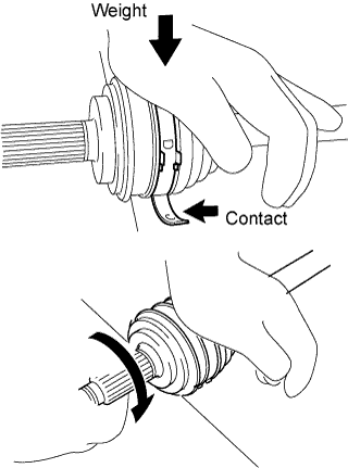
Lean your weight on your hand and roll the outboard joint forward while pressing the outboard joint against the work plane. Roll the outboard joint and fold the lever until a click sound can be heard.
- NOTICE:
- Do not damage the deflector.
- Make sure that the outboard joint is in direct contact with the work plane.
 |
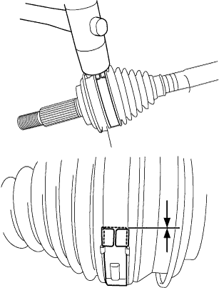
Using a plastic hammer, tap the buckle to fix it while adjusting the clearance between the lever and the groove to make the clearances between the buckle edge and the lever end even.
- NOTICE:
- Do not damage the outboard joint boot.
 |
| 5. INSTALL FRONT AXLE OUTBOARD JOINT BOOT CLAMP |
- CAUTION:
- Wear protective gloves to avoid injuries to your hands.
Install the boot clamp onto the outboard joint boot and provisionally bend the lever.
- NOTICE:
- Set the lever into the guide groove correctly.
- Check the band and the lever for any deformation before bending the lever.
 |
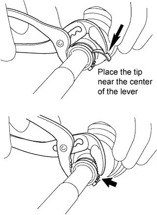
Using water pump pliers, pinch the boot clamp to provisionally fix it.
 |
Using a plastic hammer, tap the buckle to fix it while adjusting the clearance between the lever and the groove to make the clearances between the buckle edge and the lever end even.
- NOTICE:
- Do not damage the outboard joint boot.
 |
| 6. INSTALL FRONT DRIVE SHAFT DAMPER (for RH Side) |
 |
Install the drive shaft damper onto dimension (A) shown in the illustration.
- Dimension (A):
- 425.6 to 429.6 mm (16.76 to 16.91 in.)
| 7. INSTALL FRONT DRIVE SHAFT DAMPER CLAMP (for RH Side) |
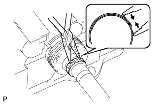 |
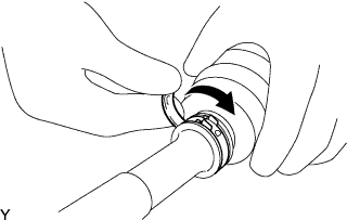
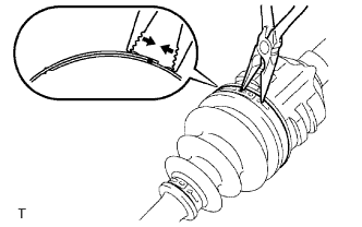
Using needle-nose pliers, align the concave part with the protrusion of a new damper clamp in order to fix it.
| 8. INSTALL FRONT DRIVE INBOARD JOINT ASSEMBLY |
Install new parts onto the outboard joint shaft in the following order.
1. Front axle inboard joint boot clamp 2. Front axle inboard joint boot 3. Front axle inboard joint boot No. 2 clamp
Fix the outboard joint shaft in a vise between aluminum plates.
- NOTICE:
- Do not overtighten the vise.
Remove the protective tape.
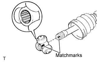
Align the matchmarks and install the tripod joint onto the outboard joint shaft.
- NOTICE:
- Face the serration side of the tripod joint outward and install it onto the outboard joint end.
 |
Using a brass bar and hammer, install the tripod joint.
- NOTICE:
- Do not hit the roller portion.
- Keep the tripod joint free of foreign matter.
Using a snap ring expander, install a new snap ring.
 |
Pack the inboard joint with grease.
- Standard Quantity:
- 125 to 135 g (4.4 to 4.8 oz.)
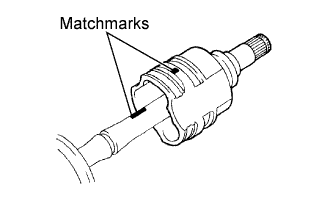
Align the matchmarks and install the inboard joint onto the outboard joint shaft.
 |
| 9. INSTALL FRONT AXLE INBOARD JOINT BOOT |
Install the inboard joint boot into the grooves of the inboard joint and outboard joint shaft.
- NOTICE:
- Keep the grooves free of grease.
| 10. INSTALL FRONT NO. 2 AXLE INBOARD JOINT BOOT CLAMP |
 |
for One-touch Clamp Type:
Install the boot clamp onto the inboard joint boot and caulk the boot clamp with a screwdriver.
- NOTICE:
- Do not damage the boot.
for Hook Clamp Type:
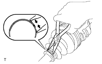
Using needle-nose pliers, align the concave part with the protrusion of the boot clamp in order to fix it.
- NOTICE:
- Do not damage the boot.
- Do not deform the claw of the hook.
 |
| 11. INSTALL FRONT AXLE INBOARD JOINT BOOT CLAMP |
 |
for One-touch Clamp Type:
Install the boot clamp onto the inboard joint boot and caulk the boot clamp with a screwdriver.
- NOTICE:
- Do not damage the boot.
for Hook Clamp Type:
Using needle-nose pliers, align the concave part with the protrusion of the boot clamp in order to fix it.
- NOTICE:
- Do not damage the boot.
- Do not deform the claw of the hook.
 |
| 12. INSPECT FRONT DRIVE SHAFT |
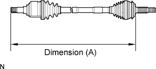 |
Check whether the drive shaft dimensions are within the following specifications.
- HINT:
- The following table shows dimension (A) of the drive shaft.
- Dimension (A):
LH RH 584.3 mm
(23.00 in.)826.3 mm
(32.53 in.)
Check for noticeable looseness when turning the joint up and down, left and right, and in the thrust direction.
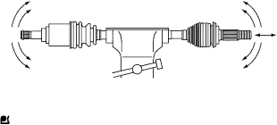 |
Check for cracks, damage and grease leakage on the boot joint.
- NOTICE:
- Keep the drive shaft level while moving it.