Theft Deterrent System (For Hatchback) Security Indicator Light Circuit
DESCRIPTION
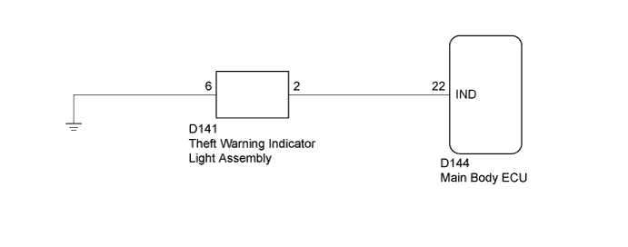
WIRING DIAGRAM
INSPECTION PROCEDURE
PERFORM ACTIVE TEST USING TECHSTREAM (SECURITY INDICATOR)
CHECK HARNESS AND CONNECTOR (MAIN BODY ECU - THEFT WARNING INDICATOR LIGHT ASSEMBLY)
INSPECT THEFT WARNING INDICATOR LIGHT ASSEMBLY
THEFT DETERRENT SYSTEM (for Hatchback) - Security Indicator Light Circuit |
DESCRIPTION
The theft warning indicator light assembly blinks continuously due to a continuous signal received from the main body ECU while in the armed state.
WIRING DIAGRAM
INSPECTION PROCEDURE
| 1.PERFORM ACTIVE TEST USING TECHSTREAM (SECURITY INDICATOR) |
Connect the Techstream to the DLC3.
Turn the ignition switch to ON.
Turn the Techstream on.
Enter the following menus: Body Electrical / Main Body / Active Test.
According to the display on the Techstream, perform the Active Test.
Main BodyTester Display
| Test Part
| Control Range
| Diagnostic Note
|
Security Indicator
| Theft warning indicator light
| OFF / ON
| -
|
- OK:
- The theft warning indicator light assembly turns on and off according to operation via the Techstream.
| 2.CHECK HARNESS AND CONNECTOR (MAIN BODY ECU - THEFT WARNING INDICATOR LIGHT ASSEMBLY) |
Disconnect the D144 main body ECU connector.
Disconnect the D141 theft warning indicator light assembly connector.
Measure the resistance according to the value(s) in the table below.
- Standard Resistance:
Tester Connection
| Condition
| Specified Condition
|
D144-22 (IND) - D141-2
| Always
| Below 1 Ω
|
D141-6 - Body ground
| Always
| Below 1 Ω
|
D144-22 (IND) - Body ground
| Always
| 10 kΩ or higher
|
| | REPAIR OR REPLACE HARNESS OR CONNECTOR |
|
|
| 3.INSPECT THEFT WARNING INDICATOR LIGHT ASSEMBLY |
Inspect the theft warning indicator light assembly (YARIS_NCP93 RM000002QCV006X.html).