Lower Instrument Panel (For Sedan) Removal
BOLTS, SCREWS AND NUTS TABLE
DISCONNECT CABLE FROM NEGATIVE BATTERY TERMINAL
REMOVE INSTRUMENT PANEL CUP HOLDER RH
REMOVE INSTRUMENT PANEL CUP HOLDER SPRING RH
REMOVE INSTRUMENT PANEL CUP HOLDER LH
REMOVE INSTRUMENT PANEL CUP HOLDER SPRING LH
REMOVE INSTRUMENT PANEL FINISH PANEL LOWER CENTER
REMOVE INSTRUMENT PANEL FINISH PANEL END LH
REMOVE INSTRUMENT PANEL FINISH PANEL END RH
REMOVE INSTRUMENT CLUSTER FINISH PANEL NO.1
REMOVE COMBINATION METER ASSEMBLY
REMOVE INSTRUMENT CLUSTER FINISH PANEL CENTER SUB-ASSEMBLY
REMOVE STEREO OPENING COVER (w/o Radio Receiver)
REMOVE RADIO RECEIVER ASSEMBLY
REMOVE AIR CONDITIONING PANEL ASSEMBLY
DISCONNECT AIR MIX DAMPER CONTROL CABLE SUB-ASSEMBLY
DISCONNECT DEFROSTER DAMPER CONTROL CABLE SUB-ASSEMBLY
DISCONNECT AIR INLET DAMPER CONTROL CABLE SUB-ASSEMBLY
SEPARATE FRONT DOOR OPENING TRIM WEATHERSTRIP RH
SEPARATE FRONT DOOR OPENING TRIM WEATHERSTRIP LH
REMOVE FRONT PILLAR GARNISH RH
REMOVE FRONT PILLAR GARNISH LH
REMOVE GLOVE COMPARTMENT DOOR ASSEMBLY
REMOVE UPPER INSTRUMENT PANEL SUB-ASSEMBLY
REMOVE FRONT DOOR SCUFF PLATE RH
REMOVE FRONT DOOR SCUFF PLATE LH
REMOVE INSTRUMENT PANEL UNDER COVER SUB-ASSEMBLY LH
REMOVE INSTRUMENT PANEL UNDER COVER SUB-ASSEMBLY RH
REMOVE COWL SIDE TRIM BOARD RH
REMOVE COWL SIDE TRIM BOARD LH
REMOVE SHIFT LEVER KNOB SUB-ASSEMBLY (for Manual Transaxle)
REMOVE UPPER CONSOLE PANEL SUB-ASSEMBLY
REMOVE CONSOLE UPPER REAR PANEL SUB-ASSEMBLY
REMOVE CONSOLE BOX CARPET
REMOVE REAR CONSOLE BOX ASSEMBLY
REMOVE INSTRUMENT PAD LOWER LH
REMOVE INSTRUMENT PAD LOWER RH
REMOVE INSTRUMENT PANEL LOWER FINISH PANEL SUB-ASSEMBLY
REMOVE INSTRUMENT PANEL BOX
DISCONNECT ANTENNA CORD SUB-ASSEMBLY
SEPARATE HOOD LOCK CONTROL LEVER SUB-ASSEMBLY
REMOVE LOWER INSTRUMENT PANEL SUB-ASSEMBLY
Lower Instrument Panel (For Sedan) -- Removal |
- HINT:
- Use the same procedure for both the RH and LH sides.
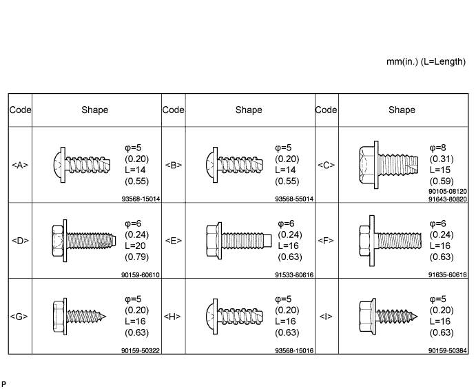
| 1. BOLTS, SCREWS AND NUTS TABLE |
- HINT:
- All bolts, screws and nuts relevant to installing and removing the instrument panel are shown, along with their alphabetic codes, in the table below.
| 2. DISCONNECT CABLE FROM NEGATIVE BATTERY TERMINAL |
Wait for at least 90 seconds after disconnecting the cable to prevent the airbag from working.
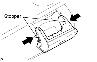
| 3. REMOVE INSTRUMENT PANEL CUP HOLDER RH |
Open the instrument panel cup holder.
Flex both sides of the instrument panel cup holder and disengage the 2 stoppers.
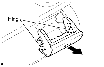
Disengage the spring.
Remove the instrument panel cup holder by moving it toward either the inside or the outside of the vehicle and disengaging the 2 hinges one at a time.
| 4. REMOVE INSTRUMENT PANEL CUP HOLDER SPRING RH |
Remove the spring.
| 5. REMOVE INSTRUMENT PANEL CUP HOLDER LH |
Open the instrument panel cup holder.
Flex both sides of the instrument panel cup holder and disengage the 2 stoppers.
Remove the instrument panel cup holder by moving it toward either the inside or the outside of the vehicle and disengaging the 2 hinges one at a time.
| 6. REMOVE INSTRUMENT PANEL CUP HOLDER SPRING LH |
Remove the spring.
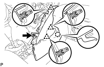
| 7. REMOVE INSTRUMENT PANEL FINISH PANEL LOWER CENTER |
Disengage the 2 claws and 2 clips and remove the instrument panel finish panel lower center.
| 8. REMOVE INSTRUMENT PANEL FINISH PANEL END LH |
Disengage the 6 claws and 3 clips and remove the instrument panel finish panel end LH.
| 9. REMOVE INSTRUMENT PANEL FINISH PANEL END RH |
Disengage the 6 claws and 3 clips and remove the instrument panel finish panel end RH.
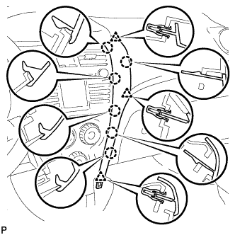
| 10. REMOVE INSTRUMENT CLUSTER FINISH PANEL NO.1 |
Disengage the 7 claws and 5 clips and remove the instrument cluster finish panel.
| 11. REMOVE COMBINATION METER ASSEMBLY |
Disconnect the 2 connectors.
Remove the 2 screws and pull the combination meter rearward to remove it.
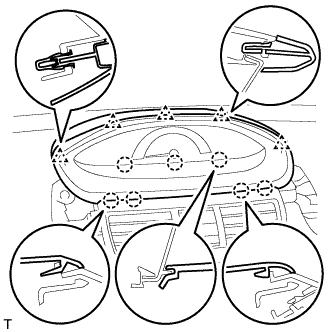
| 12. REMOVE INSTRUMENT CLUSTER FINISH PANEL CENTER SUB-ASSEMBLY |
Disengage the 2 claws and 4 clips and remove the instrument cluster panel center.
| 13. REMOVE STEREO OPENING COVER (w/o Radio Receiver) |
Remove the 4 screws and remove the stereo opening cover.
| 14. REMOVE RADIO RECEIVER ASSEMBLY |
for Integrated with Panel:
Disconnect the hazard warning signal switch connector.
Remove the 4 bolts.
Disengage the 4 clips and the 4 claws and remove the radio receiver.
Disconnect the plug.
Disconnect the 3 radio connectors.
except Integrated with Panel:
Remove the 4 bolts and the radio receiver.
Disconnect the plug.
Disconnect the 2 radio connectors.
| 15. REMOVE AIR CONDITIONING PANEL ASSEMBLY |
Disengage the 4 clips and 2 claws and remove the air conditioning panel.
Disconnect the 3 connectors and 4 clamps.
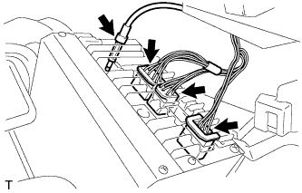
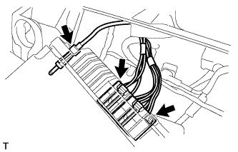
| 16. DISCONNECT AIR MIX DAMPER CONTROL CABLE SUB-ASSEMBLY |
Disconnect the air mix damper control cable from the clamp.
Disengage the 2 claws and disconnect the air mix damper control cable.
| 17. DISCONNECT DEFROSTER DAMPER CONTROL CABLE SUB-ASSEMBLY |
Disengage the 2 claws and disconnect the defroster damper control cable.
| 18. DISCONNECT AIR INLET DAMPER CONTROL CABLE SUB-ASSEMBLY |
Disengage the 2 claws and disconnect the air inlet damper control cable.
| 19. SEPARATE FRONT DOOR OPENING TRIM WEATHERSTRIP RH |
(YARIS_NCP93 RM000001EEX047X_01_0015.html)
| 20. SEPARATE FRONT DOOR OPENING TRIM WEATHERSTRIP LH |
(YARIS_NCP93 RM000001EEX047X_01_0038.html)
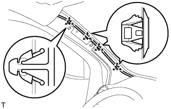
| 21. REMOVE FRONT PILLAR GARNISH RH |
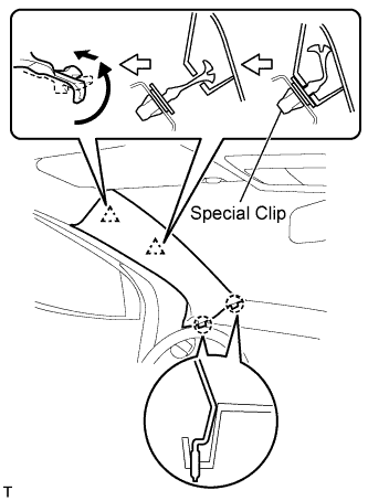
w/ Curtain Shield Airbag:
- NOTICE:
- Install a protective cover onto the curtain shield airbag as soon as the front pillar garnish is removed.
- Replace the special clip with a new one when the front pillar garnish is removed.
Disengage the 2 clips and the 2 claws and remove the front pillar garnish.
w/o Curtain Shield Airbag:
Disengage the 2 clips and the 2 claws and remove the front pillar garnish.
Disconnect the antenna connector.
Using a clip remover, remove the 3 clamps.
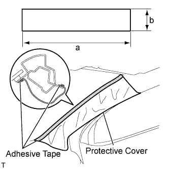
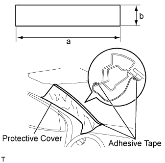
w/ Curtain Shield Airbag:
Completely cover the curtain shield airbag with a piece of cloth or nylon and fix the ends of the fabric with adhesive tape, as shown in the illustration.
- Protective cover size:
Area
| Measurement
|
a
| 700 mm (27.56 in.)
|
b
| 120 mm (4.72 in.)
|
| 22. REMOVE FRONT PILLAR GARNISH LH |
w/ Curtain Shield Airbag:
- NOTICE:
- Install a protective cover onto the curtain shield airbag as soon as the front pillar garnish is removed.
- Replace the special clip with a new one when the front pillar garnish is removed.
Disengage the 2 clips and the 2 claws and remove the front pillar garnish.
w/o Curtain Shield Airbag:
Disengage the 2 clips and the 2 claws and remove the front pillar garnish.
Using a clip remover, remove the 4 clamps.
w/ Curtain Shield Airbag:
Completely cover the curtain shield airbag with a piece of cloth or nylon and fix the ends of the fabric with adhesive tape, as shown in the illustration.
- Protective cover size:
Area
| Measurement
|
a
| 700 mm (27.56 in.)
|
b
| 120 mm (4.72 in.)
|
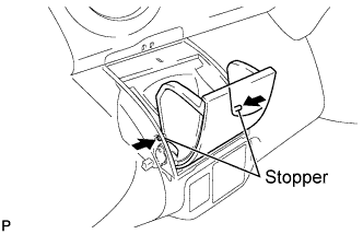
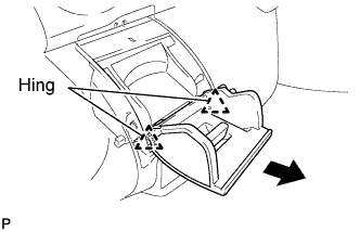
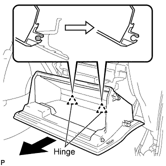
| 23. REMOVE GLOVE COMPARTMENT DOOR ASSEMBLY |
Disengage the claw and separate the 2 glove compartment door stoppers from the glove compartment door.
Slightly flex the upper part of the glove compartment door to release the 2 stoppers and open the glove compartment door assembly until it becomes horizontal.
Pull the glove compartment door assembly out horizontally to disengage the hinge portion and remove the glove compartment door.
- NOTICE:
- Pull the glove compartment door out horizontally, otherwise, installation failure caused by excessive play around the hinge portion will result.
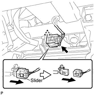
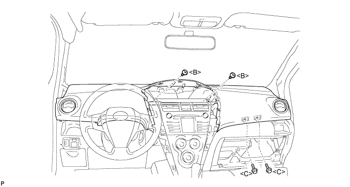
| 24. REMOVE UPPER INSTRUMENT PANEL SUB-ASSEMBLY |
Slide the slider and disconnect the passenger airbag connector.
Disconnect the clamp.
Remove the 2 <C> bolts and 2 <B> screws.
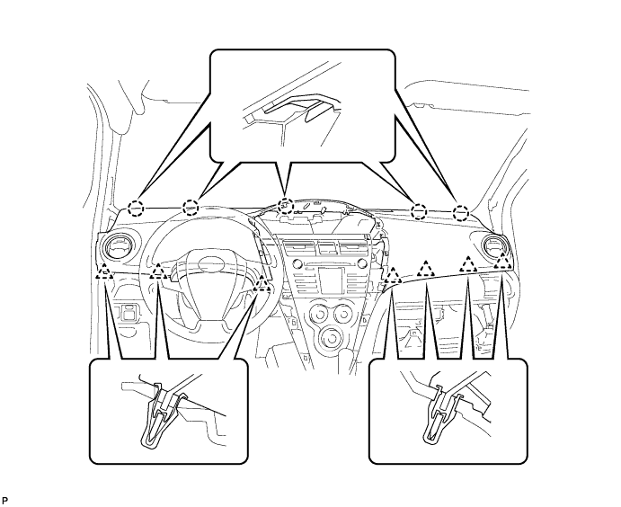
Disengage the 7 clips by lifting the rear side of the instrument panel up.
While lifting the instrument panel, slide it toward the rear of the vehicle. Disengage the 5 claws from the front side of the instrument panel and remove the instrument panel.
| 25. REMOVE FRONT DOOR SCUFF PLATE RH |
Disengage the 7 claws and remove the rear door scuff plate.
| 26. REMOVE FRONT DOOR SCUFF PLATE LH |
- HINT:
- Use the same procedure as for the RH side.
| 27. REMOVE INSTRUMENT PANEL UNDER COVER SUB-ASSEMBLY LH |
Remove the 2 screws.
Disengage the 3 claws and remove the instrument panel under cover.
| 28. REMOVE INSTRUMENT PANEL UNDER COVER SUB-ASSEMBLY RH |
Disengage the 4 claws and remove the instrument panel under cover.
| 29. REMOVE COWL SIDE TRIM BOARD RH |
Disengage the claw and the stud bolt and remove the cowl side trim board.
| 30. REMOVE COWL SIDE TRIM BOARD LH |
- HINT:
- Use the same procedure as for the RH side.
| 31. REMOVE SHIFT LEVER KNOB SUB-ASSEMBLY (for Manual Transaxle) |
Remove the shift lever knob.
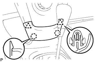
| 32. REMOVE UPPER CONSOLE PANEL SUB-ASSEMBLY |
Shift the shift lever into the N position.
Disengage the 5 clips and the claw and remove the upper console panel.
| 33. REMOVE CONSOLE UPPER REAR PANEL SUB-ASSEMBLY |
Disengage the 3 clips and 3 claws.
Disconnect the connector and remove the console upper rear panel.
| 34. REMOVE CONSOLE BOX CARPET |
Remove the console box carpet.
| 35. REMOVE REAR CONSOLE BOX ASSEMBLY |
Disconnect the clamp.
Remove the 2 bolts and 2 screws.
Disengage the 4 claws and remove the rear console box.
| 36. REMOVE INSTRUMENT PAD LOWER LH |
Remove screw <I>.
Disengage the claw and 3 clips and remove the instrument panel pad lower.
| 37. REMOVE INSTRUMENT PAD LOWER RH |
Remove screw <I>.
Disengage the claw and 3 clips and remove the instrument panel pad lower.
| 38. REMOVE INSTRUMENT PANEL LOWER FINISH PANEL SUB-ASSEMBLY |
Disengage the 7 claws and open the instrument panel lower finish panel.
Remove the 2 <A> screws and remove the instrument panel lower finish panel.
| 39. REMOVE INSTRUMENT PANEL BOX |
Open the instrument panel box.
Pull the instrument panel box out horizontally with the instrument panel open and disengage the 2 hinges.
Remove the stopper of the instrument panel box from the cutout of the instrument panel lower and remove the instrument panel box.
| 40. DISCONNECT ANTENNA CORD SUB-ASSEMBLY |
Disconnect the 5 antenna cord clamps.
| 41. SEPARATE HOOD LOCK CONTROL LEVER SUB-ASSEMBLY |
Disengage the 3 claws and separate the hood lock control lever.
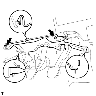
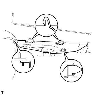
| 42. REMOVE LOWER INSTRUMENT PANEL SUB-ASSEMBLY |
Disengage the 2 claws and disconnect the DLC3 connector.
Disconnect the clamps and connectors.
Remove the 6 <D> bolts, 2 <E> bolts, screw <G> and screw <H> and remove the lower instrument panel.