Lower Instrument Panel (For Sedan) Installation
INSTALL LOWER INSTRUMENT PANEL SUB-ASSEMBLY
CONNECT HOOD LOCK CONTROL LEVER SUB-ASSEMBLY
CONNECT ANTENNA CORD SUB-ASSEMBLY
INSTALL INSTRUMENT PANEL BOX
INSTALL INSTRUMENT PANEL LOWER FINISH PANEL SUB-ASSEMBLY
INSTALL INSTRUMENT PAD LOWER RH
INSTALL INSTRUMENT PAD LOWER LH
INSTALL REAR CONSOLE BOX ASSEMBLY
INSTALL CONSOLE BOX CARPET
INSTALL CONSOLE UPPER REAR PANEL SUB-ASSEMBLY
INSTALL UPPER CONSOLE PANEL SUB-ASSEMBLY
INSTALL SHIFT LEVER KNOB SUB-ASSEMBLY (for Manual Transaxle)
INSTALL COWL SIDE TRIM BOARD RH
INSTALL COWL SIDE TRIM BOARD LH
INSTALL INSTRUMENT PANEL UNDER COVER SUB-ASSEMBLY RH
INSTALL INSTRUMENT PANEL UNDER COVER SUB-ASSEMBLY LH
INSTALL FRONT DOOR SCUFF PLATE RH
INSTALL FRONT DOOR SCUFF PLATE LH
INSTALL UPPER INSTRUMENT PANEL SUB-ASSEMBLY
INSTALL GLOVE COMPARTMENT DOOR ASSEMBLY
INSTALL FRONT PILLAR GARNISH RH
INSTALL FRONT PILLAR GARNISH LH
INSTALL FRONT DOOR OPENING TRIM WEATHERSTRIP RH
INSTALL FRONT DOOR OPENING TRIM WEATHERSTRIP LH
CONNECT AIR INLET DAMPER CONTROL CABLE SUB-ASSEMBLY
CONNECT DEFROSTER DAMPER CONTROL CABLE SUB-ASSEMBLY
CONNECT AIR MIX DAMPER CONTROL CABLE SUB-ASSEMBLY
INSTALL AIR CONDITIONING PANEL ASSEMBLY
INSTALL STEREO OPENING COVER (w/o Radio Receiver)
INSTALL RADIO RECEIVER ASSEMBLY
INSTALL INSTRUMENT CLUSTER FINISH PANEL CENTER SUB-ASSEMBLY
INSTALL COMBINATION METER ASSEMBLY
INSTALL INSTRUMENT CLUSTER FINISH PANEL NO.1
INSTALL INSTRUMENT PANEL FINISH PANEL END RH
INSTALL INSTRUMENT PANEL FINISH PANEL END LH
INSTALL INSTRUMENT PANEL FINISH PANEL LOWER CENTER
INSTALL INSTRUMENT PANEL CUP HOLDER SPRING RH
INSTALL INSTRUMENT PANEL CUP HOLDER RH
INSTALL INSTRUMENT PANEL CUP HOLDER SPRING LH
INSTALL INSTRUMENT PANEL CUP HOLDER LH
CONNECT CABLE TO NEGATIVE BATTERY TERMINAL
CHECK SRS WARNING LIGHT
Lower Instrument Panel (For Sedan) -- Installation |
| 1. INSTALL LOWER INSTRUMENT PANEL SUB-ASSEMBLY |
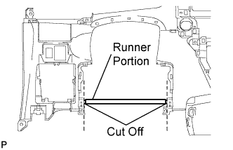
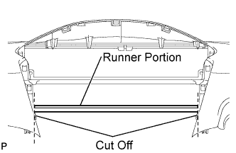
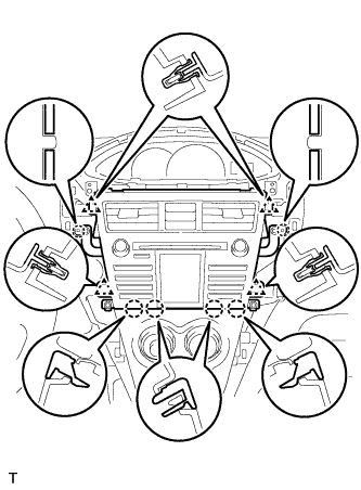
Using a nipper, cut off both ends of the runner portion shown in the illustration (When installing a new one).
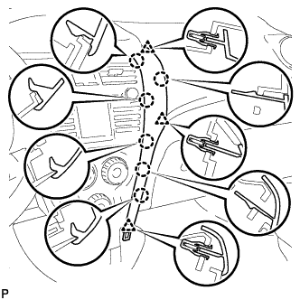
Install the lower instrument panel with the 6 <D> bolts, 2 <E> bolts, screw <G> and screw <H>.
- NOTICE:
- Do not excessively tighten the <D> bolts, as this may damage the area not being tightened.
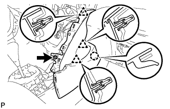
Connect the clamps and connectors.
Engage the 2 claws and connect the DLC3 connector.
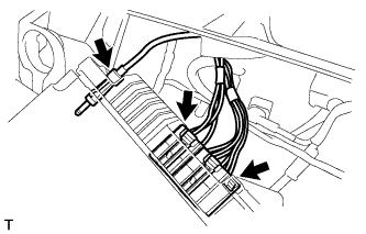
| 2. CONNECT HOOD LOCK CONTROL LEVER SUB-ASSEMBLY |
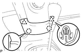
Engage the 3 claws to connect the control lever.
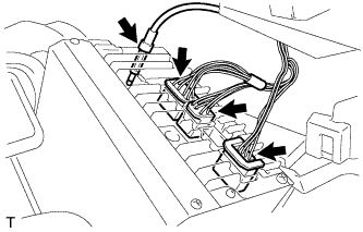
| 3. CONNECT ANTENNA CORD SUB-ASSEMBLY |
Connect the 5 antenna cord clamps.
| 4. INSTALL INSTRUMENT PANEL BOX |
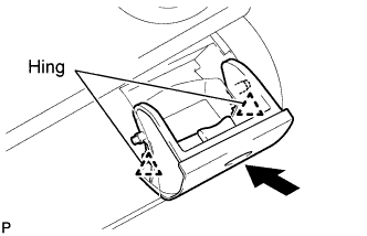
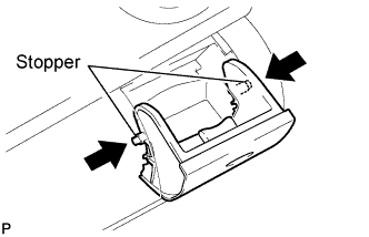
Insert the stopper of the instrument panel box from the cutout of the instrument panel lower.
Engage the 2 hinges with the instrument panel open.
Close the instrument panel box.
| 5. INSTALL INSTRUMENT PANEL LOWER FINISH PANEL SUB-ASSEMBLY |
Install the 2 <A> screws.
Engage the 7 claws and install the instrument panel lower finish panel.
| 6. INSTALL INSTRUMENT PAD LOWER RH |
Engage the claw and 3 clips and install the instrument pad lower.
Install screw <I>.
| 7. INSTALL INSTRUMENT PAD LOWER LH |
Engage the claw and 3 clips and install the instrument pad lower.
Install screw <I>.
| 8. INSTALL REAR CONSOLE BOX ASSEMBLY |
Engage the 4 claws and install the rear console box.
Install the 2 bolts and 2 screws.
Connect the clamp.
| 9. INSTALL CONSOLE BOX CARPET |
Install the console box carpet.
| 10. INSTALL CONSOLE UPPER REAR PANEL SUB-ASSEMBLY |
Connect the connector.
Engage the 3 clips and 3 claws and install the console upper rear panel.
| 11. INSTALL UPPER CONSOLE PANEL SUB-ASSEMBLY |
Engage the 5 clips and the claw and install the upper console panel.
| 12. INSTALL SHIFT LEVER KNOB SUB-ASSEMBLY (for Manual Transaxle) |
Install the shift lever knob.
| 13. INSTALL COWL SIDE TRIM BOARD RH |
Engage the stud bolt and the claw and install the cowl side trim board.
| 14. INSTALL COWL SIDE TRIM BOARD LH |
- HINT:
- Use the same procedure as for the RH side.
| 15. INSTALL INSTRUMENT PANEL UNDER COVER SUB-ASSEMBLY RH |
Engage the 4 claws and install the instrument panel under cover.
| 16. INSTALL INSTRUMENT PANEL UNDER COVER SUB-ASSEMBLY LH |
Engage the 3 claws and install the instrument panel under cover.
Tighten the 2 screws.
| 17. INSTALL FRONT DOOR SCUFF PLATE RH |
Engage the 11 claws and install the front door scuff plate.
| 18. INSTALL FRONT DOOR SCUFF PLATE LH |
- HINT:
- Use the same procedure as for the RH side.
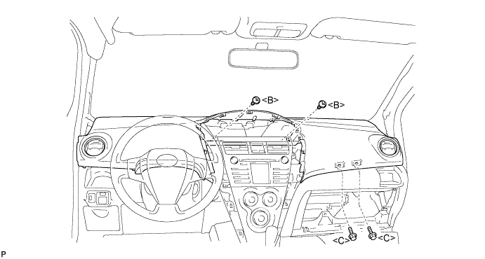
| 19. INSTALL UPPER INSTRUMENT PANEL SUB-ASSEMBLY |
Using a nipper, cut off both ends of the runner portion shown in the illustration (When installing a new one).
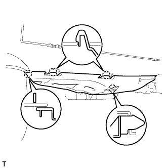
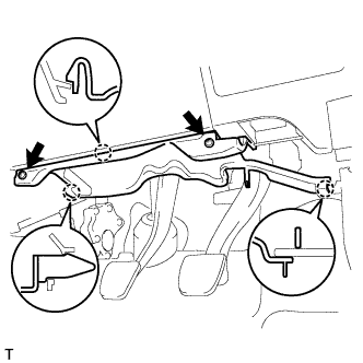
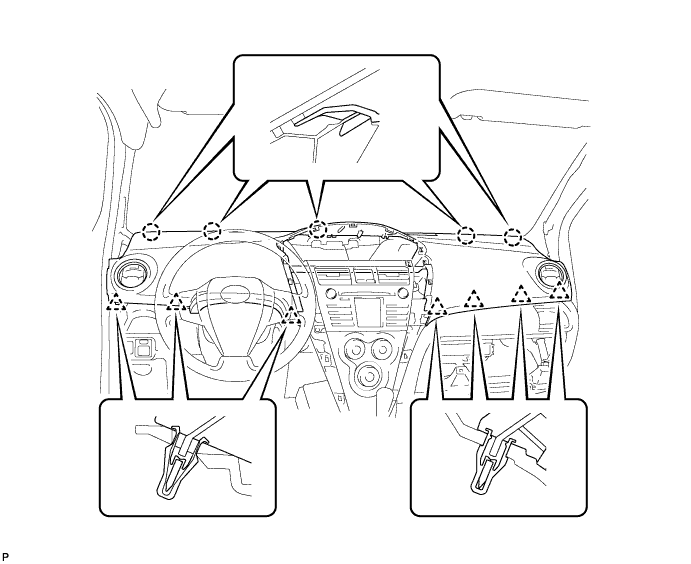
Engage the 5 claws at the front side of the instrument panel.
Engage the 7 clips at the rear side of the instrument panel.
Install the upper instrument panel with the 2 <C> bolts and the 2 <B> screws.
- Torque:
- 20 N*m{204 kgf*cm, 15 ft.*lbf} for bolt <C>
Connect the passenger airbag connector and clamp.
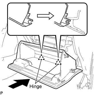
| 20. INSTALL GLOVE COMPARTMENT DOOR ASSEMBLY |
Engage the claws of the hinge portions by pushing the glove compartment door in the horizontal direction to install the glove compartment door assembly.
- NOTICE:
- Engage the claw by pushing it in the horizontal direction, otherwise, installation failure caused by excessive play around the hinge portion will result.
Slightly flex the upper portion of the glove compartment door assembly to engage the stopper.
Install the 2 glove compartment door stoppers onto the glove compartment door.
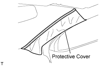
| 21. INSTALL FRONT PILLAR GARNISH RH |
w/ Curtain Shield Airbag:
Remove the piece of cloth or nylon.
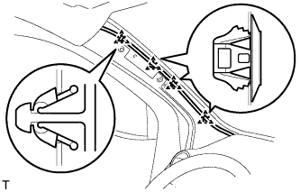
Install the 3 clamps.
Connect the antenna connector.
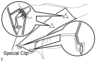
w/ Curtain Shield Airbag:
Install 2 new special clips and the clip onto the front pillar garnish.
Engage the 2 clips and the 2 claws and install the front pillar garnish.
w/o Curtain Shield Airbag:
Engage the 2 clips and the 2 claws and install the front pillar garnish.
| 22. INSTALL FRONT PILLAR GARNISH LH |
w/ Curtain Shield Airbag:
Remove the piece of cloth or nylon.
Install the 4 clamps.
w/ Curtain Shield Airbag:
Install 2 new special clips and the clip onto the front pillar garnish.
Engage the 2 clips and the 2 claws and install the front pillar garnish.
w/o Curtain Shield Airbag:
Engage the 2 clips and the 2 claws and install the front pillar garnish.
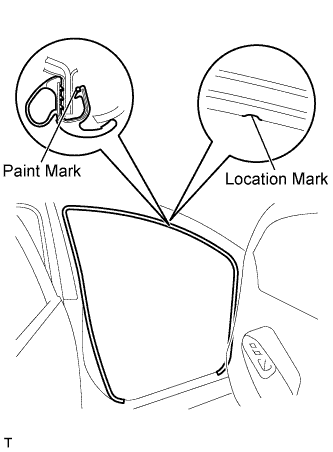
| 23. INSTALL FRONT DOOR OPENING TRIM WEATHERSTRIP RH |
Align the location mark with the paint mark first, and install the front door opening trim weatherstrip, as shown in the illustration.
- Paint mark:
Area
| Color
|
RH side
| Blue
|
LH side
| Pink
|
| 24. INSTALL FRONT DOOR OPENING TRIM WEATHERSTRIP LH |
- HINT:
- Use the same procedure as for the RH side.
| 25. CONNECT AIR INLET DAMPER CONTROL CABLE SUB-ASSEMBLY |
Engage the 2 claws and connect the air inlet damper control cable.
| 26. CONNECT DEFROSTER DAMPER CONTROL CABLE SUB-ASSEMBLY |
Engage the 2 claws and connect the defroster damper control cable.
| 27. CONNECT AIR MIX DAMPER CONTROL CABLE SUB-ASSEMBLY |
Engage the 2 claws and connect the air mix control cable clamp.
Connect the air mix damper control cable to the clamp.
| 28. INSTALL AIR CONDITIONING PANEL ASSEMBLY |
Connect the 3 connectors and the 4 clamps.
Engage the 4 clips and 2 claws and install the air conditioning panel.
| 29. INSTALL STEREO OPENING COVER (w/o Radio Receiver) |
Install the stereo opening cover with the 4 screws.
| 30. INSTALL RADIO RECEIVER ASSEMBLY |
for Integrated with Panel:
Connect the plug.
Connect the 3 radio connectors.
Align the 2 bosses of the instrument panel with the hole in the radio bracket.
Engage the 4 clips and 4 claws and install the radio receiver.
Tighten the 4 bolts.
Connect the hazard warning signal switch connector.
except Integrated with Panel:
Connect the plug.
Connect the 2 radio connectors.
Align the 2 bosses of the instrument panel with the hole in the radio bracket.
Install the radio receiver with the 4 bolts.
| 31. INSTALL INSTRUMENT CLUSTER FINISH PANEL CENTER SUB-ASSEMBLY |
Engage the 2 claws and 4 clips and install the instrument cluster finish panel center.
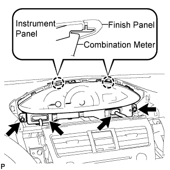
| 32. INSTALL COMBINATION METER ASSEMBLY |
Install the combination meter assembly with the 2 screws.
- NOTICE:
- Install the meter by inserting the ribbed portions of the meter between the instrument panel and meter cluster.
Connect the 2 connectors.
| 33. INSTALL INSTRUMENT CLUSTER FINISH PANEL NO.1 |
Fit the 2 claws of the instrument cluster finish panel into the upper instrument cluster finish panel center.
Engage the 5 claws and 5 clips and install the instrument cluster finish panel.
| 34. INSTALL INSTRUMENT PANEL FINISH PANEL END RH |
Engage the 6 claws and 3 clips and install the instrument panel finish panel end RH.
| 35. INSTALL INSTRUMENT PANEL FINISH PANEL END LH |
Engage the 6 claws and 3 clips and install the instrument panel finish panel end LH.
| 36. INSTALL INSTRUMENT PANEL FINISH PANEL LOWER CENTER |
Engage the 2 claws and 2 clips and install the instrument panel finish panel lower center.
| 37. INSTALL INSTRUMENT PANEL CUP HOLDER SPRING RH |
Install the spring.
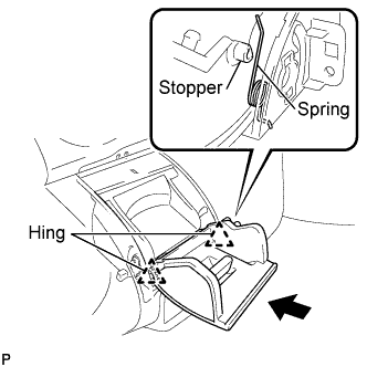
| 38. INSTALL INSTRUMENT PANEL CUP HOLDER RH |
Install the 2 hinges of the cup holder one at a time.
Engage the spring with the instrument panel cup holder.
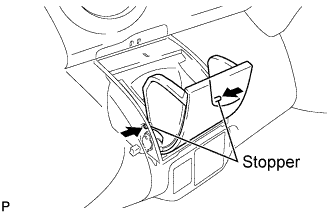
Flex both sides of the cup holder and engage the 2 stoppers.
Close the instrument panel cup holder.
| 39. INSTALL INSTRUMENT PANEL CUP HOLDER SPRING LH |
Install the spring.
| 40. INSTALL INSTRUMENT PANEL CUP HOLDER LH |
Install the 2 hinges of the cup holder one at a time.
- HINT:
- Make sure that the spring is set in the position shown in the illustration.
Flex both sides of the cup holder and engage the 2 stoppers.
Close the instrument panel cup holder.
| 41. CONNECT CABLE TO NEGATIVE BATTERY TERMINAL |
- Torque:
- 5.4 N*m{55 kgf*cm, 48 in.*lbf}
| 42. CHECK SRS WARNING LIGHT |
(YARIS_NCP93 RM000000XFD0CVX.html)