INSTALL DRIVE PLATE AND RING GEAR SUB-ASSEMBLY (for Automatic Transaxle)
INSTALL AUTOMATIC TRANSAXLE ASSEMBLY (for Automatic Transaxle)
INSPECT AND ADJUST CLUTCH COVER ASSEMBLY (for Manual Transaxle)
INSTALL DRIVE PLATE AND TORQUE CONVERTER CLUTCH SETTING BOLT (for Automatic Transaxle)
INSTALL FLYWHEEL HOUSING UNDER COVER (for Automatic Transaxle)
INSTALL CLUTCH RELEASE CYLINDER ASSEMBLY (for Manual Transaxle)
INSTALL COMPRESSOR ASSEMBLY WITH PULLEY (w/ Air Conditioning System)
INSTALL TRANSMISSION CONTROL CABLE ASSEMBLY (for Automatic Transaxle)
INSTALL TRANSMISSION CONTROL CABLE ASSEMBLY (for Manual Transaxle)
Engine Assembly (For Sedan) -- Installation |
| 1. INSTALL ENGINE MOUNTING INSULATOR LH |
- HINT:
- Only perform this procedure when replacement of the engine mounting insulator LH is necessary.
Install the engine mounting insulator LH with the 5 bolts.
- Torque:
- 50 N*m{530 kgf*cm, 38 ft.*lbf}
| 2. INSTALL DRIVE SHAFT HEAT INSULATOR SUB-ASSEMBLY |
Install the drive shaft heat insulator sub-assembly with the bolt and nut.
- Torque:
- 18 N*m{183 kgf*cm, 13 ft.*lbf}
| 3. INSTALL ENGINE WIRE |
Connect all the sensor connectors and wire harness clamps to the engine assembly and install the engine wire harness.
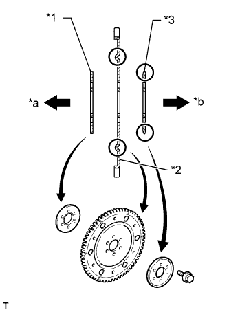
| 4. INSTALL DRIVE PLATE AND RING GEAR SUB-ASSEMBLY (for Automatic Transaxle) |
Hold the crankshaft with SST.
- SST
- 09960-10010(09962-01000,09963-01000)
Clean the 6 bolts and their holes.
Apply adhesive to the 2 or 3 end threads of the bolt.
Text in Illustration *1 Adhesive - NOTICE:
- Do not start the engine for at least 1 hour after installation.
- Adhesive:
- Toyota Genuine Adhesive 1324, Three bond 1324 or equivalent
 |
Install the rear drive plate spacer, drive plate and ring gear sub-assembly, and front drive plate spacer with the 6 bolts.
Text in Illustration *1 Front Drive Plate Spacer *2 Drive Plate and Ring Gear *3 Rear Drive Plate Spacer *a Engine Side *b Transaxle Side
 |
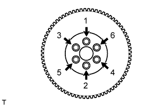
Install and uniformly tighten the 6 bolts in several steps, in the sequence shown in the illustration.
- Torque:
- 88 N*m{897 kgf*cm, 65 ft.*lbf}
 |
| 5. INSTALL AUTOMATIC TRANSAXLE ASSEMBLY (for Automatic Transaxle) |
Make sure that the knock pin is installed on the engine side.
Install the automatic transaxle with torque converter with the 7 bolts.
- Torque:
- 30 N*m{301 kgf*cm, 22 ft.*lbf}
- CAUTION:
- Make sure that the torque converter rotates.
| 6. INSTALL FLYWHEEL SUB-ASSEMBLY (for Manual Transaxle) |
Hold the crankshaft with SST.
- SST
- 09960-10010(09962-01000,09963-01000)
Clean the 6 bolts and their holes.
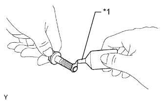
Apply adhesive to the end 2 or 3 threads of new bolts.
- Adhesive:
- Toyota Genuine Adhesive 1324, Three Bond 1324 or equivalent
Text in Illustration *1 Adhesive
 |
Install the flywheel with the 6 bolts in the order shown in the illustration.
- Torque:
- 49 N*m{500 kgf*cm, 38 ft.*lbf}
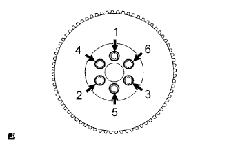 |
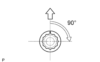
Mark a paint mark on each bolt head on the engine upper side.
Tighten the bolts 90° in the sequence shown in the illustration.
- NOTICE:
- Do not start the engine for at least 1 hour after performing the installation.
 |
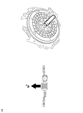
| 7. INSTALL CLUTCH DISC ASSEMBLY (for Manual Transaxle) |
Insert SST into the clutch disc assembly, then insert them both into the flywheel sub-assembly.
Text in Illustration *a Flywheel Side - SST
- 09301-00210
- NOTICE:
- Insert the clutch disc assembly in the correct direction.
 |
| 8. INSTALL CLUTCH COVER ASSEMBLY (for Manual Transaxle) |
Align the matchmark on the clutch cover assembly with that on the flywheel sub-assembly.
Text in Illustration *a Temporally *b matchmarks
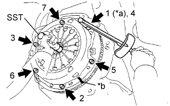 |
Following the procedures shown in the illustration, tighten the 6 bolts in order, starting with the bolt located near the knock pin at the top.
- Torque:
- 19 N*m{195 kgf*cm, 14 ft.*lbf}
- HINT:
- Following the order in the illustration, tighten the blots evenly one at a time.
- Move SST up and down, right and left lightly after checking that the disc is in the center, and tighten the bolts.
- SST
- 09301-00210
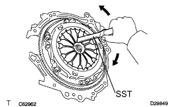
| 9. INSPECT AND ADJUST CLUTCH COVER ASSEMBLY (for Manual Transaxle) |
 |
Using a dial indicator with a roller instrument, check the diaphragm spring tip alignment.
- Maximum non-alignment:
- 0.5 mm (0.020 in.)
If the alignment is not as specified, using SST, adjust the diaphragm spring tip alignment.
- SST
- 09333-00013
 |
| 10. INSTALL MANUAL TRANSAXLE ASSEMBLY (for Manual Transaxle) |
Align the input shaft with the clutch disc and install the manual transaxle onto the engine.
Install the 7 bolts.
- Torque:
- 33 N*m{336 kgf*cm, 24 ft.*lbf}
 |
| 11. INSTALL CONTROL CABLE BRACKET (for Manual Transaxle) |
 |
Install the control cable bracket with the 2 bolts.
- Torque:
- 25 N*m{250 kgf*cm, 18 ft.*lbf}
| 12. INSTALL STARTER ASSEMBLY |
 |
Install the starter assembly with the 2 bolts.
- Torque:
- 37 N*m{377 kgf*cm, 27 ft.*lbf}
Connect the connector.
Connect terminal 30 with the nut.
- Torque:
- 9.8 N*m{100 kgf*cm, 87 in.*lbf}
Close the terminal cap.
| 13. INSTALL FLYWHEEL HOUSING SIDE COVER |
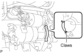 |
Insert the protruding portion into the end of the cylinder block and while pushing it along the cylinder block, fit the 2 claws into the cylinder block.
- NOTICE:
- Make sure that the claw makes a click sound, indicating that it fits tightly.
- Replace the claw with a new one if it does not fit tightly or is deformed.
| 14. INSTALL FRONT SUSPENSION CROSSMEMBER SUB-ASSEMBLY |
Install the engine moving control rod with the through bolt.
- Torque:
- 120 N*m{1,224 kgf*cm, 89 ft.*lbf}
Remove the 2 bolts and remove the 2 engine hangers.
Install the oxygen sensor wiring bracket with the bolt.
- Torque:
- 60 N*m{612 kgf*cm, 44 ft.*lbf}
Install the radio setting condenser with the bolt.
- Torque:
- 40 N*m{408 kgf*cm, 30 ft.*lbf}
| 15. INSTALL ENGINE ASSEMBLY WITH TRANSAXLE |
Set the engine assembly with transaxle and front suspension crossmember on the engine lifter.
Operate the engine lifter and lift the engine assembly with transaxle and front suspension crossmember to the position where the engine mounting insulators RH and LH can be installed.
Install the engine mounting insulator LH with the through bolt and nut.
- Torque:
- 52 N*m{530 kgf*cm, 38 ft.*lbf}
Install the engine mounting insulator RH with the 5 bolts and nut.
- Torque:
- 52 N*m{530 kgf*cm, 38 ft.*lbf}
Operate the engine lifter and provisionally install the engine assembly with transaxle and front suspension crossmember onto the vehicle with the 6 bolts.
Insert SST into the datum holes of the front suspension crossmembers RH and LH alternately and tighten bolts A, B and C on both sides in several sequences.
- SST
- 09670-00010
- Torque:
- 87 N*m{887 kgf*cm, 64 ft.*lbf}for Bolt A
- 151 N*m{1540 kgf*cm, 111 ft.*lbf}for Bolt B
- 98 N*m{999 kgf*cm, 72 ft.*lbf}for Bolt C
- CAUTION:
- Insert SST into the datum hole vertically.
- If impossible to insert SST vertically, loosen all the bolts and then insert SST again.
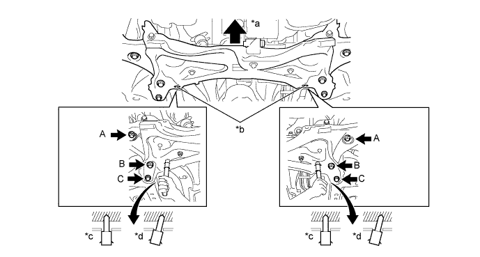
Text in Illustration *a Front *b Datum Hole *c OK *d NG
| 16. INSTALL DRIVE PLATE AND TORQUE CONVERTER CLUTCH SETTING BOLT (for Automatic Transaxle) |
Tighten the 6 torque converter set bolts.
- Torque:
- 27 N*m{275 kgf*cm, 20 ft.*lbf}
| 17. INSTALL FLYWHEEL HOUSING UNDER COVER (for Automatic Transaxle) |
| 18. INSTALL FRONT DRIVE SHAFT ASSEMBLY |
| 19. INSTALL EXHAUST PIPE ASSEMBLY FRONT |
| 20. INSTALL NO. 1 STEERING COLUMN HOLE COVER SUB-ASSEMBLY |
Install clip B onto the body portion and install the steering column hole cover onto the body portion with clip A.
- NOTICE:
- Make sure that the lip portion of steering column hole cover is not damaged.
| 21. INSTALL STEERING SLIDING YOKE SUB-ASSEMBLY |
Align the matchmarks and install the steering sliding yoke sub-assembly onto the power steering gear.
Text in Illustration *1 Steering Sliding Yoke Sub-assembly *a Matchmarks
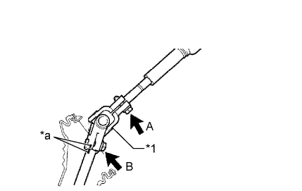 |
Install the bolt B.
- Torque:
- 35 N*m{360 kgf*cm, 26 ft.*lbf}
Tighten bolt A.
- Torque:
- 35 N*m{360 kgf*cm, 26 ft.*lbf}
| 22. INSTALL COLUMN HOLE COVER SILENCER SHEET |
Install the column hole cover silencer sheet with the 2 clips.
Install the floor carpet.
| 23. CONNECT ENGINE WIRE |
Install the earth wire of the engine room wire harness with the bolt.
Connect the 2 engine wire harness connectors and wire harness clamp to the engine room junction block.
Connect the engine wire harness connector to the ECM.
| 24. INSTALL CLUTCH RELEASE CYLINDER ASSEMBLY (for Manual Transaxle) |
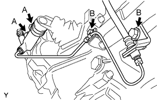 |
Install the clutch release cylinder and clutch pipe with the 4 bolts.
- Torque:
- 12 N*m{120 kgf*cm, 8.7 ft.*lbf} for bolt A
- 12 N*m{122 kgf*cm, 8.9 ft.*lbf} for bolt B
| 25. INSTALL COMPRESSOR ASSEMBLY WITH PULLEY (w/ Air Conditioning System) |
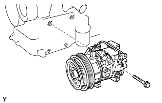 |
Provisionally tighten the compressor with the bolt.
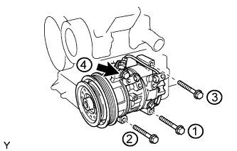
Tighten the compressor with the 4 bolts.
- Torque:
- 25 N*m{255 kgf*cm, 18 ft.*lbf}
- NOTICE:
- Tighten the bolts in the sequence shown in the illustration to install the compressor.
 |
Connect the connector.
| 26. INSTALL FAN AND GENERATOR V BELT |
Provisionally install the fan and generator V belt onto each pulley.
- NOTICE:
- Make sure that there is no foreign matter or liquid, such as oil, on the belt and pulleys.
- Make sure that the V belt is securely fitted into the rib grooves of the pulley.
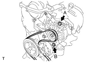
| 27. ADJUST FAN AND GENERATOR V BELT |
Insert an adjusting bar between the engine mounting bracket and generator assembly. Pull the adjusting bar toward the vehicle front to adjust the generator V belt tension (YARIS_NCP93 RM000001DCH00ZX_01_0001.html).
Text in Illustration *a OK *b NG - NOTICE:
- Do not insert the adjusting bar between the camshaft timing oil control valve assembly and generator assembly. It could damage the camshaft timing oil control valve assembly.
 |
First tighten bolt A, then tighten bolt B.
- Torque:
- 19 N*m{189 kgf*cm, 14 ft.*lbf} for bolt A
- 54 N*m{551 kgf*cm, 40 ft.*lbf} for bolt B
 |
| 28. CONNECT FUEL TUBE SUB-ASSEMBLY |
Connect the fuel tube connector and fuel pipe, and install No. 1 fuel pipe clamp.
- CAUTION:
- Align the fuel tube connector with the pipe, then push the fuel tube connector in until the retainer makes a click sound. If the connection is tight, apply a small amount of engine oil to the the tip of the pipe. After connecting, pull the pipe and connector to make sure that they are securely connected.
| 29. CONNECT HEATER WATER HOSE INLET A |
Connect heater water inlet hose A to the heater unit.
| 30. CONNECT HEATER WATER OUTLET HOSE A |
Connect heater water outlet hose A to the heater unit.
| 31. CONNECT UNION TO CHECK VALVE HOSE |
Connect the union to check valve hose to the booster vacuum tube.
| 32. INSTALL TRANSMISSION CONTROL CABLE ASSEMBLY (for Automatic Transaxle) |
 |
Install the transmission control cable onto the control shaft lever with the nut.
- Torque:
- 12 N*m{122 kgf*cm, 9 ft.*lbf}
Install the transmission control cable into the bracket with the new clip.
| 33. INSTALL TRANSMISSION CONTROL CABLE ASSEMBLY (for Manual Transaxle) |
Connect the 2 cable ends and install the 2 washers and the 2 clips.
Install 2 new clips onto the control cable bracket.
| 34. INSTALL NO. 2 CYLINDER HEAD COVER |
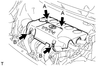 |
Tighten the 2 A nuts, then the 2 B nuts.
- Torque:
- 7.0 N*m{71 kgf*cm, 62 in.*lbf}
| 35. CONNECT OIL COOLER INLET HOSE (for Automatic Transaxle) |
Connect the oil cooler inlet hose with the clip.
| 36. CONNECT OIL COOLER OUTLET HOSE (for Automatic Transaxle) |
Connect the oil cooler outlet hose with the clip.
| 37. CONNECT NO. 2 RADIATOR HOSE |
Connect No. 2 radiator hose to the water inlet.
| 38. CONNECT RADIATOR RESERVOIR TANK HOSE |
Connect the radiator reservoir tank hose to the water filler.
| 39. CONNECT NO. 3 RADIATOR HOSE |
Connect No. 3 radiator hose to the water filler.
| 40. INSTALL BATTERY CARRIER |
Install the battery carrier with the 5 bolts.
- Torque:
- 17 N*m{173 kgf*cm, 13 ft.*lbf}
Install the clamp.
| 41. INSTALL AIR CLEANER BRACKET |
Install the air cleaner bracket with the 2 bolts.
- Torque:
- 19 N*m{194 kgf*cm, 14 ft.*lbf}
Connect the wire harness clamp to the air cleaner bracket.
| 42. INSTALL FUEL VAPOR FEED HOSE ASSEMBLY |
Connect the fuel vapor feed hose assembly to the cylinder head cover and purge pipe.
| 43. INSTALL AIR CLEANER ASSEMBLY |
Install the air cleaner case with air cleaner inlet No. 1 with the 2 bolts.
- Torque:
- 7.8 N*m{80 kgf*cm, 69 in.*lbf}
Connect the wire harness to the air cleaner case.
Install the air cleaner element.
Install and lock the air cleaner cap and the air cleaner hose and then tighten the air cleaner hose clamp.
- Torque:
- 4.0 N*m{41 kgf*cm, 35 in.*lbf}
Connect the ventilation hose to the air cleaner hose.
Connect the vacuum switching valve connector and the wire harness clamp.
Connect the fuel vapor feed hose to the vacuum switching valve assembly and air cleaner hose.
Connect the intake air flow meter connector and the wire harness clamp.
| 44. INSTALL COWL TOP PANEL OUTER |
Install the cowl top panel outer with the 8 bolts.
- Torque:
- 6.5 N*m{66 kgf*cm, 58 in.*lbf}
Install the cowl top to cowl inner brace with the 2 bolts.
- Torque:
- 6.5 N*m{66 kgf*cm, 58 in.*lbf}
Connect the wire harness clamp.
| 45. INSTALL FRONT AIR SHUTTER SEAL RH |
Engage the 3 claws to install the front air shutter seal RH.
| 46. INSTALL FRONT WIPER MOTOR AND LINK |
Connect the connector.
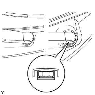
 |
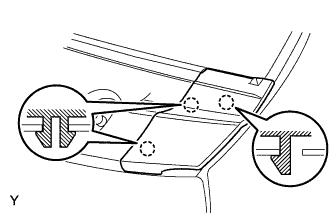
Slide the wiper link as shown in the illustration and engage the rubber pin with the body.
Install the front wiper motor and link with the 2 bolts.
- Torque:
- 5.5 N*m{56 kgf*cm, 49 in.*lbf}
| 47. INSTALL COWL TOP VENTILATOR LOUVER SUB-ASSEMBLY |
Connect the washer hoses.
 |
Engage the 5 hooks.
Engage the 8 hooks and the 4 claws.
 |
Install the cowl top ventilator louver sub-assembly with the 3 clips.
| 48. INSTALL COWL SIDE VENTILATOR SUB-ASSEMBLY LH |
Engage the 3 claws and install the cowl side ventilator sub-assembly LH.
 |
| 49. INSTALL COWL SIDE VENTILATOR SUB-ASSEMBLY RH |
- HINT:
- Use the same procedure as for the LH side.
| 50. INSTALL FRONT WIPER ARM AND BLADE ASSEMBLY LH |
Scrape any metal powder off the serrated part of the wiper arm with a round file or the equivalent (when reinstalling).
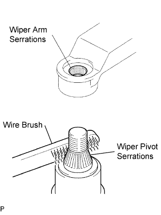 |
Clean the wiper pivot serrations with a wire brush.
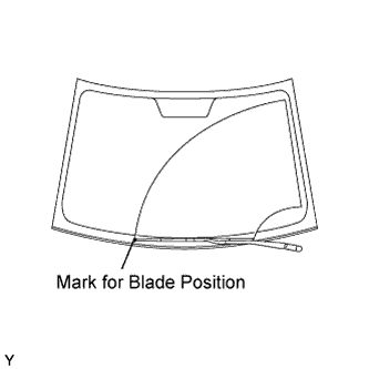
Operate the wiper, then stop the windshield wiper motor in the automatic stop position.
Align the blade tip with the mark on the windshield glass, as shown in the illustration.
 |
Tighten the nut of the front wiper arm.
- Torque:
- 26 N*m{265 kgf*cm, 19 ft.*lbf}
| 51. INSTALL FRONT WIPER ARM AND BLADE ASSEMBLY RH |
Scrape any metal powder off the serrated part of the wiper arm with a round file or the equivalent (when reinstalling).
|
Clean the wiper pivot serrations with a wire brush.
Operate the wiper, then stop the windshield wiper motor in the automatic stop position.
Align the blade tip with the mark on the windshield glass, as shown in the illustration.
 |
Tighten the nut of the front wiper arm.
- Torque:
- 26 N*m{265 kgf*cm, 19 ft.*lbf}
| 52. INSTALL FRONT WIPER ARM HEAD CAP |
Engage the claw and install the 2 front wiper arm head caps.
 |
| 53. INSTALL BATTERY TRAY |
| 54. INSTALL BATTERY |
Install the battery onto the vehicle with the battery clamp.
- Torque:
- 3.5 N*m{36 kgf*cm, 31 in.*lbf}
Connect the cable to the battery terminal.
- Torque:
- 5.4 N*m{55 kgf*cm, 48 in.*lbf}
| 55. ADD ENGINE COOLANT |
Tighten all the plugs.
Pour engine coolant into the radiator assembly until it overflows.
- Capacity:
- M/T 4.8 liters (5.1 USqts, 4.5 lmp. qts)
- A/T 4.7 liters (5.0 USqts, 4.4 lmp. qts)
- NOTICE:
- Do not substitute water for engine coolant.
- HINT:
- Use of improper engine coolant may damage the engine coolant system.
- Use only Toyota Super Long Life Coolant or similar high quality ethylene glycol based non-silicate, non-amine, non-nitrite, and non-borate engine coolant with long-life hybrid organic acid technology (coolant with long-life hybrid organic acid technology consists of a combination of low phosphates and organic acids).
Check the engine coolant level inside the radiator assembly by squeezing the inlet and outlet radiator hoses several times by hand. If the engine coolant level goes down, add engine coolant.
Install the radiator cap sub-assembly securely.
Slowly pour engine coolant into the radiator reservoir until it reaches the FULL line.
Bleed air from the cooling system.
Warm up the engine until the thermostat opens. While the thermostat is open, circulate the coolant for several minutes.
- HINT:
- The thermostat open timing can be confirmed by pressing the No. 2 radiator hose by hand, and checking when when the coolant starts to flow inside the hose.
Maintain the engine speed at 2,000 to 2,500 rpm and warm up the engine until the cooling fan operates.
Press the No. 2 radiator hose and No. 3 radiator hose several times by hand to bleed air.
- NOTICE:
- When pressing the radiator houses
- Wear protective glove.
- Be careful as the radiator hoses are hot.
- Keep your hands away form the radiator fan.
Stop the engine and wait until the coolant cools down.
If the engine coolant level is below the full level, perform steps (b) through (g) again and repeat the operation until the engine coolant level stays at the full level.
Recheck the engine coolant level inside the radiator reservoir tank assembly. If it is below the full level, add engine coolant.
| 56. ADD AUTOMATIC TRANSAXLE FLUID (for Automatic Transaxle) |
| Classification | Capacity (Reference) | |
| Toyota Genuine ATF WS or equivalent | Dry fill | 6.4 liters (6.8 US qts, 5.6 Imp. qts) |
| Drain and refill | 2.5 liters (2.6 US qts, 2.2 Imp. qts) | |
| 57. INSPECT AUTOMATIC TRANSAXLE FLUID (for Automatic Transaxle) |
 |
- HINT:
- Drive the vehicle until the engine and transaxle are at normal operating temperature.
- Fluid temperature:
- 70 to 80 °C (158 to 176 °F)
Park the vehicle on a level surface and engage the parking brake.
With the engine idling and the brake pedal depressed, shift the shift lever into all positions from P to L, and then return it to the P position.
Pull out the oil level gauge and wipe it clean.
Push it fully back into the pipe.
Pull it out and check that the fluid level is within the HOT range.
If there is any leakage, repair or replace O-rings, FIPGs, oil seals, plugs or other parts.
| 58. ADD MANUAL TRANSAXLE OIL (for Manual Transaxle) |
Install a new gasket and the drain plug.
- Torque:
- 39 N*m{400 kgf*cm, 29 ft.*lbf}
Add manual transaxle oil.
Text in Illustration *a 0 to 5 mm (0 to 0.196 in.)
 |
Install the transmission filler plug and a new gasket.
- Torque:
- 39 N*m{400 kgf*cm, 29 ft.*lbf}
| 59. INSPECT MANUAL TRANSAXLE OIL (for Manual Transaxle) |
|
| *a | 0 to 5 mm (0 to 0.196 in.) |
Stop the vehicle in a level place.
Remove the transmission filler plug and the gasket.
Check that the oil surface is within 5 mm (0.20 in.) of the bottom of the transmission filler plug opening.
- NOTICE:
- Excessively large or small amounts of oil may cause problems.
- After replacing the oil, drive the vehicle and check the oil level again.
Check for oil leakage when the oil level is low.
Install the transmission filler plug and a new gasket.
- Torque:
- 39 N*m{400 kgf*cm, 29 ft.*lbf}
| 60. INSPECT FAN AND GENERATOR V BELT |
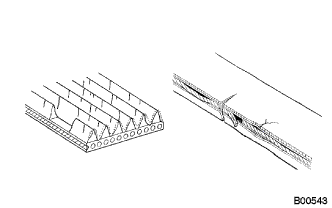 |
Check the belt for wear, cracks or other signs of damage.
If any of the following defects is found, replace the V-ribbed belt.- HINT:
- The belt is cracked.
- The belt is worn out to the extent that the wires are exposed.
- The belt has chunks missing from the ribbed groves.
Check that the belt fits properly in the ribbed grooves.
Text in Illustration *a CORRECT *b INCORRECT - HINT:
- Check with your hand, to confirm that the belt has not slipped out of the grooves on the bottom to the pulley. If it has slipped out, replace the V-ribbed belt. Install a new V-ribbed belt correctly.
 |
Inspect the V belt deflection and tension.
Text in Illustration *A w/o Air Conditioner *B w/ Air Conditioner - Deflection:
Item Specified Condition New belt 8.0 to 9.0 mm (0.31 to 0.35 in) Used belt 12.5 to 13.5 mm (0.49 to 0.53 in)
- Tension:
Item Specified Condition New belt 700 to 800 N (71 to 82 kg, 157 to 180 lb) Used belt 300 to 400 N (31 to 41 kg, 67 to 90 lb)
- HINT:
- When inspecting the V belt deflection, apply 98 N (10 kgf) tensile force to it.
- Perform the V belt inspection and adjustment while the engine is cold.
- V-ribbed belt tension and deflection should be checked immediately after installation of a new belt, and after cranking the engine when inspecting a used belt.
- Check the V belt deflection at the point between the specified pulleys where the deflection is greatest.
- When installing a new belt, set its tension to the intermediate value of the specification.
- When inspecting a belt which has been used for over 5 minutes, apply the Used Belt specifications.
- When reinstalling a belt which has been used for over 5 minutes, adjust its deflection and tension to the intermediate values of each Used Belt specification.
- V-ribbed belt tension and deflection should be checked after 2 revolutions of engine cranking.
- When using a belt tension gauge, confirm its accuracy by using a master gauge first.
 |
| 61. INSPECT FOR FUEL LEAK |
When using the Techstream.
Connect the Techstream to the DLC3.
Turn the ignition switch to ON and turn the tester ON.
- NOTICE:
- Do not start the engine.
Select the following menu items: Powertrain / Engine and ECT / Active Test / Control the Fuel Pump / Speed.
- HINT:
- Refer to the Techstream operator's manual for further details.
Check that there is no fuel leakage anywhere on the fuel system after doing maintenance.
| 62. INSPECT FOR ENGINE OIL LEAK |
| 63. INSPECT FOR EXHAUST GAS LEAK |
| 64. INSPECT FOR ENGINE COOLANT LEAK |
- CAUTION:
- To avoid the danger of being burned, do not remove the water filler cap sub-assembly while the engine and radiator assembly are still hot. Thermal expansion will cause hot engine coolant and steam to blow out from the radiator assembly.
Fill the radiator assembly with engine coolant, and attach a radiator cap tester.
 |
Pump the tester to 118 kPa (1.2 kgf/cm2, 17.1 psi), and then check that the pressure does not drop.
If the pressure drops, check the hoses, radiator assembly and water pump assembly for leaks. If there are no signs or traces of external engine coolant leaks, check the heater core, cylinder block and head.
| 65. INSTALL ENGINE UNDER COVER RH |
| 66. INSTALL ENGINE UNDER COVER LH |
| 67. INSTALL FRONT WHEELS |
- Torque:
- 103 N*m{1,050 kgf*cm, 76 ft.*lbf}
| 68. INSPECT IGNITION TIMING |
When using the Techstream:
Warm up and stop the engine.
Connect the Techstream to the DLC3.
Turn the ignition switch to ON.
Select the following menu items:
Powertrain / Engine and ECT / Data List / Active Test / Connect the TC and TE1 / ON.- HINT:
- Refer to the Techstream operator's manual for further details.
Inspect the ignition timing during idling.
- Ignition timing:
- 8 to 12 degrees BTDC
- NOTICE:
- Turn all the electrical systems and the A/C off.
- Inspect the ignition timing with the cooling fan off.
- When checking the ignition timing, shift the transmission to the neutral position.
Turn the ignition switch off.
Disconnect the Techstream from the DLC3.
When not using the Techstream:
Remove cylinder head cover No. 2 (YARIS_NCP93 RM000001EFJ02JX_01_0002.html).
Warm up and stop the engine.
Connect the clip of the timing light to the wire harness, as shown in the illustration.
- NOTICE:
- Use a timing light that detects the first signal.
Turn the ignition switch to ON.
Using SST, connect terminals 13 (TC) and 4 (CG) of the DLC3.
- SST
- 09843-18040
- NOTICE:
- Examine the terminal numbers before connecting them. Connecting the wrong terminals could damage the engine.
Inspect the ignition timing during idling.
- Ignition timing:
- 8 to 12 degrees BTDC
- NOTICE:
- Turn all the electrical systems and the A/C off.
- Inspect the ignition timing with the cooling fan off.
- When checking the ignition timing, shift the transmission to the neutral position.
Disconnect terminals 13 (TC) and 4 (CG) of the DLC3.
Turn the ignition switch off.
Remove the timing light.
Install cylinder head cover No. 2 (YARIS_NCP93 RM000001EFH02JX_01_0002.html).


| 69. INSPECT ENGINE IDLING SPEED |
When using the Techstream:
Warm up and stop the engine.
Connect the Techstream to the DLC3.
Turn the ignition switch to ON.
Select the following menu items:
Powertrain / Engine and ECT / Data List / Engine Speed.- HINT:
- Refer to the Techstream operator's manual for further details.
Inspect the engine idling speed.
- Idling speed:
- 600 to 700 rpm for manual transaxle
- 650 to 750 rpm for automatic transaxle
- NOTICE:
- Turn all the electrical systems and the A/C off.
- Inspect the idling speed with the cooling fan off.
- When checking the idling speed, shift the transmission to either the neutral position or the parking position.
Turn the ignition switch off.
Disconnect the Techstream from the DLC3.
When not using the Techstream.
Warm up and stop the engine.
Install SST to terminal 9 (TAC) of the DLC3, then connect a tachometer.
- SST
- 09843-18040
- NOTICE:
- Examine the terminal numbers before connecting them. Connecting the wrong terminals could damage the engine.
Turn the ignition switch to ON.
Inspect the engine idling speed.
- Idling speed:
- 600 to 700 rpm for manual transaxle
- 650 to 750 rpm for automatic transaxle
Turn the ignition switch off.
Disconnect the tachometer.
Remove SST from terminal 9 (TAC).

| 70. INSPECT CO/HC |
Start the engine.
Run the engine at 2,500 rpm for approximately 180 seconds.
Insert the CO/HC meter testing probe at least 40 cm (1.3 ft) into the tailpipe while idling.
Check the CO/HC concentration during idling and when running at 2,500 rpm.
- HINT:
- When doing the 2 mode (with the engine idling/running at 2,500 rpm) test, the measuring procedures are determined by applicable local regulations.
Check the air fuel ratio sensor operation (YARIS_NCP93 RM000001CK803GX.html).
Check the heated oxygen sensor operation (YARIS_NCP93 RM000001CK803HX.html).
See the table below for possible causes, then inspect the applicable parts and repair them if necessary.
CO HC Problems Possible Causes Normal High Rough idling - Faulty ignition:
- Incorrect timing
- Fouled, shorted or improperly gapped plugs
- Incorrect valve clearance
- Leakage from intake and exhaust valves
- Leakage from cylinders
Low High Rough idling
(Fluctuating HC reading)- Vacuum leaks:
- PCV hoses
- Intake manifold
- Throttle body
- Brake booster line
- Lean mixture causing misfire
High High Rough idling
(Black smoke from exhaust)- Restricted air cleaner filter element
- Plugged PCV valve
- Faulty EFI systems:
- Faulty pressure regulator
- Faulty engine coolant temperature sensor
- Faulty mass air flow meter
- Faulty ECM
- Faulty injectors
- Throttle body
- Faulty ignition:
| 71. INSPECT FRONT WHEEL ALIGNMENT |
| 72. INSPECT ABS SENSOR SIGNAL (w/ ABS) |