Can Communication System (For Sedan) -- Terminals Of Ecu |
- NOTICE:
- Turn the ignition switch off before measuring the resistances of the CAN main wire and the CAN branch wire.
- After the ignition switch is turned off, check that the key reminder warning system and light reminder warning system are not in operation.
- Before measuring the resistance, leave the vehicle as is for at least 1 minute and do not operate the ignition switch, any other switches or the doors. If doors need to be opened in order to check connectors, open the doors and leave them open.
- HINT:
- Operating the ignition switch, any switches or any doors triggers related ECU and sensor communication with the CAN, which causes resistance variation.
| JUNCTION CONNECTOR |
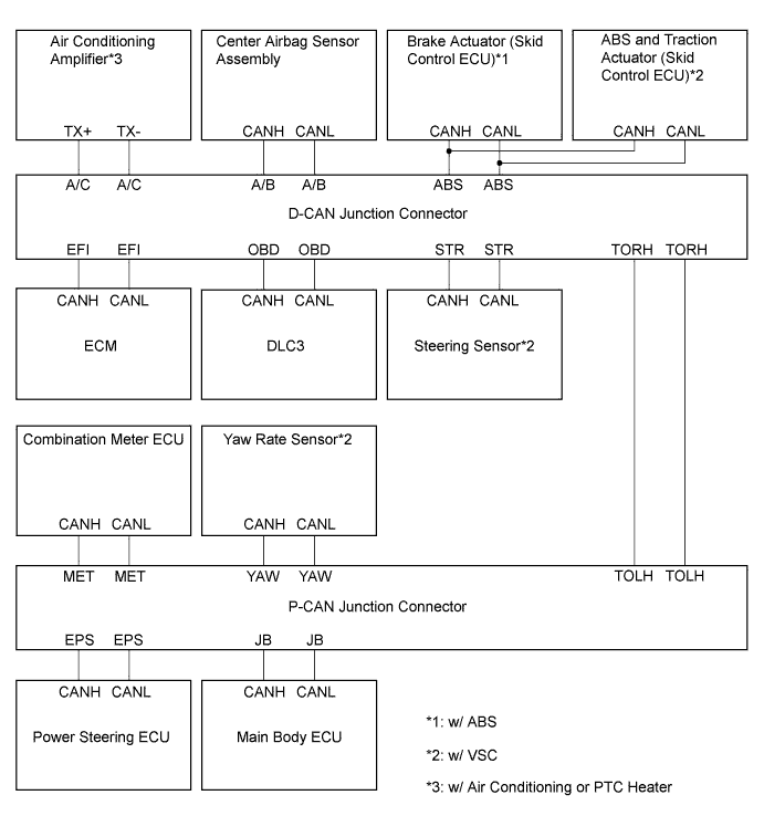
D-CAN Junction Connector
Text in Illustration *1 Front view of wire harness connector
(to D-CAN Junction Connector)
*1: w/ ABS or VSCD-CAN Junction Connector Terminal No. (Symbol) Wiring Color Skid Control ECU*1 (CAN-H) D41-1 (ABS) G Skid Control ECU*1 (CAN-L) D41-12 (ABS) W Steering Sensor (CAN-H) D41-2 (STR) SB Steering Sensor (CAN-L) D41-13 (STR) W DLC3 (CAN-H) D41-3 (OBD) V DLC3 (CAN-L) D41-14 (OBD) W ECM (CAN-H) D41-4 (EFI) L ECM (CAN-L) D41-15 (EFI) W Air Conditioning Amplifier*2 (CAN-H) D41-6 (A/C) V Air Conditioning Amplifier*2 (CAN-L) D41-17 (A/C) W Center Airbag Sensor Assembly (CAN-H) D41-8 (A/B) B Center Airbag Sensor Assembly (CAN-L) D41-19 (A/B) W CAN Main Wire (between D-CAN and P-CAN Junction Connector) D41-11 (TORH) Y CAN Main Wire (between D-CAN and P-CAN Junction Connector) D41-22 (TORH) W
*2: w/ Air Conditioning or PTC Heater
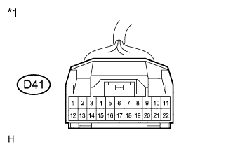 |
| JUNCTION CONNECTOR |
P-CAN Junction Connector
Text in Illustration *1 Front view of wire harness connector
(to P-CAN Junction Connector)P-CAN Junction Connector Terminal No. (Symbol) Wiring Color Yaw Rate Sensor (CAN-H) D42-2 (YAW) BE Yaw Rate Sensor (CAN-L) D42-13 (YAW) W Power Steering ECU (CAN-H) D42-4 (EPS) SB Power Steering ECU (CAN-L) D42-15 (EPS) W Main Body ECU (CAN-H) D42-5 (JB) R Main Body ECU (CAN-L) D42-16 (JB) W Combination Meter ECU (CAN-H) D42-7 (MET) G Combination Meter ECU (CAN-L) D42-18 (MET) W CAN Main Wire (between P-CAN and D-CAN Junction Connector) D42-11 (TOLH) Y CAN Main Wire (between P-CAN and D-CAN Junction Connector) D42-22 (TOLH) W Wiring diagram for identifying CAN junction connectors
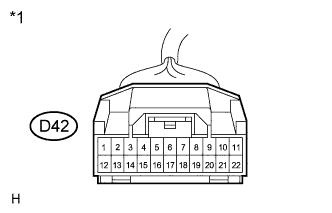 |
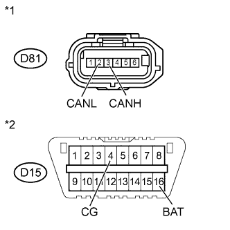
| DLC3 |
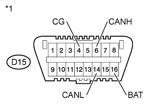 |
Turn the ignition switch off.
Measure the resistance according to the value(s) in the table below.
Text in Illustration *1 DLC3 Standard Resistance Terminal No. (Symbol) Wiring Color Switch Condition Specified Condition D15-6 (CANH) - D15-14 (CANL) V - W Ignition switch off 54 to 69 Ω D15-6 (CANH) - D15-4 (CG) V - W-B Ignition switch off 200 Ω or higher D15-14 (CANL) - D15-4 (CG) W - W-B Ignition switch off 200 Ω or higher D15-6 (CANH) - D15-16 (BAT) V - SB Ignition switch off 6 kΩ or higher D15-14 (CANL) - D15-16 (BAT) W - SB Ignition switch off 6 kΩ or higher
| BRAKE ACTUATOR (SKID CONTROL ECU) (w/ ABS) |
Turn the ignition switch off.
Disconnect the A15 brake actuator (skid control ECU) connector.
Measure the resistance according to the value(s) in the table below.
Text in Illustration *1 Front view of wire harness connector
(to Brake Actuator (Skid Control ECU))Standard Resistance Terminal No. (Symbol) Wiring Color Switch Condition Specified Condition A15-25 (CANH) - A15-14 (CANL) G - W Ignition switch off 54 to 69 Ω A15-25 (CANH) - A15-1 (GND1) G - W-B Ignition switch off 200 Ω or higher A15-14 (CANL) - A15-1 (GND1) W - W-B Ignition switch off 200 Ω or higher A15-25 (CANH) - A15-12 (+BS) G - W Ignition switch off 6 kΩ or higher A15-25 (CANL) - A15-12 (+BS) W - W Ignition switch off 6 kΩ or higher
 |
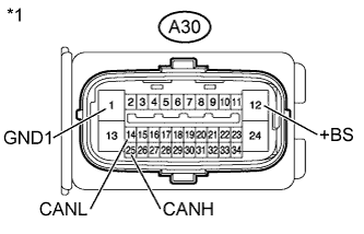
| ABS AND TRACTION ACTUATOR (SKID CONTROL ECU) (w/ VSC) |
Turn the ignition switch off.
Disconnect the A30 ABS and traction actuator (skid control ECU) connector.
Measure the resistance according to the value(s) in the table below.
Text in Illustration *1 Front view of wire harness connector
(to ABS and Traction Actuator (Skid Control ECU))Standard Resistance Terminal No. (Symbol) Wiring Color Switch Condition Specified Condition A30-25 (CANH) - A30-14 (CANL) G - W Ignition switch off 54 to 69 Ω A30-25 (CANH) - A30-1 (GND1) G - W-B Ignition switch off 200 Ω or higher A30-14 (CANL) - A30-1 (GND1) W - W-B Ignition switch off 200 Ω or higher A30-25 (CANH) - A30-12 (+BS) G - W Ignition switch off 6 kΩ or higher A30-14 (CANL) - A30-12 (+BS) W - W Ignition switch off 6 kΩ or higher
 |
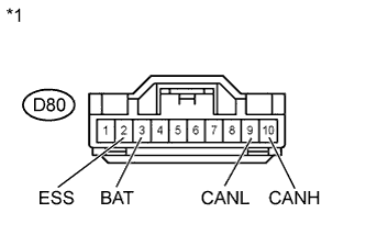
| STEERING SENSOR (w/ VSC) |
Turn the ignition switch off.
Disconnect the D80 steering sensor connector.
Measure the resistance according to the value(s) in the table below.
Text in Illustration *1 Front view of wire harness connector
(to Steering Sensor)Standard Resistance Terminal No. (Symbol) Wiring Color Switch Condition Specified Condition D80-10 (CANH) - D80-9 (CANL) SB - W Ignition switch off 54 to 69 Ω D80-10 (CANH) - D80-2 (ESS) SB - W-B Ignition switch off 200 Ω or higher D80-9 (CANL) - D80-2 (ESS) W - W-B Ignition switch off 200 Ω or higher D80-10 (CANH) - D80-3 (BAT) SB - LG Ignition switch off 6 kΩ or higher D80-9 (CANL) - D80-3 (BAT) W - LG Ignition switch off 6 kΩ or higher
 |
| YAW RATE SENSOR (w/ VSC) |
- HINT:
- For vehicle with VSC only.
Turn the ignition switch off.
Disconnect the D81 yaw rate sensor connector.
Measure the resistance according to the value(s) in the table below.
Text in Illustration *1 Front view of wire harness connector
(to Yaw Rate Sensor)*2 DLC3 Standard Resistance Terminal No. (Symbol) Wiring Color Switch Condition Specified Condition D81-3 (CANH) - D81-2 (CANL) BE - W Ignition switch off 54 to 69 Ω D81-3 (CANH) - D15-4 (CG) BE - W-B Ignition switch off 200 Ω or higher D81-2 (CANL) - D15-4 (CG) W - W-B Ignition switch off 200 Ω or higher D81-3 (CANH) - D15-16 (BAT) BE - SB Ignition switch off 6 kΩ or higher D81-2 (CANL) - D15-16 (BAT) W - SB Ignition switch off 6 kΩ or higher
 |
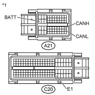
| ECM |
Turn the ignition switch off.
Disconnect the A21 and C20 ECM connectors.
Measure the resistance according to the value(s) in the table below.
Text in Illustration *1 Front view of wire harness connector
(to ECM)Standard Resistance Terminal No. (Symbol) Wiring Color Switch Condition Specified Condition A21-41 (CANH) - A21-49 (CANL) L - W Ignition switch off 108 to 132 Ω A21-41 (CANH) - C20-104 (E1) L - W Ignition switch off 200 Ω or higher A21-49 (CANL) - C20-104 (E1) W - W Ignition switch off 200 Ω or higher A21-41 (CANH) - A21-20 (BATT) L - Y Ignition switch off 6 kΩ or higher A21-49 (CANL) - A21-20 (BATT) W - Y Ignition switch off 6 kΩ or higher
 |
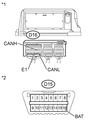
| CENTER AIRBAG SENSOR ASSEMBLY |
Turn the ignition switch off.
Disconnect the D16 center airbag sensor assembly connector.
Measure the resistance according to the value(s) in the table below.
Text in Illustration *1 Rear view of wire harness connector
(to Center Airbag Sensor Assembly)*2 DLC3 Standard Resistance Terminal No. (Symbol) Wiring Color Switch Condition Specified Condition D16-13 (CANH) - D16-22 (CANL) B - W Ignition switch off 54 to 69 Ω D16-13 (CANH) - D16-25 (E1) B - W-B Ignition switch off 200 Ω or higher D16-22 (CANL) - D16-25 (E1) W - W-B Ignition switch off 200 Ω or higher D16-13 (CANH) - D15-16 (BAT) B - SB Ignition switch off 6 kΩ or higher D16-22 (CANL) - D15-16 (BAT) W - SB ignition switch off 6 kΩ or higher
 |
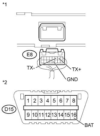
| AIR CONDITIONING AMPLIFIER (w/ Air Conditioning or PTC Heater) |
Turn the ignition switch off.
Disconnect the E8 air conditioning amplifier connector.
Measure the resistance according to the value(s) in the table below.
Text in Illustration *1 Rear view of wire harness connector
(to Air Conditioning Amplifier)*2 DLC3 Standard Resistance Terminal No. (Symbol) Wiring Color Switch Condition Specified Condition E8-2 (TX+) - E8-3 (TX-) V - W Ignition switch off 54 to 69 Ω E8-2 (TX+) - E8-12 (GND) V - W-B Ignition switch off 200 Ω or higher E8-3 (TX-) - E8-12 (GND) W - W-B Ignition switch off 200 Ω or higher E8-2 (TX+) - D15-16 (BAT) V - SB Ignition switch off 6 kΩ or higher E8-3 (TX-) - D15-16 (BAT) W - SB Ignition switch off 6 kΩ or higher
 |
| MAIN BODY ECU |

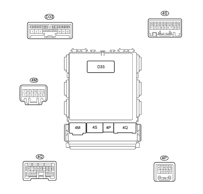
Turn the ignition switch off.
Disconnect the D33, 4B and 4E main body ECU connectors.
Measure the resistance according to the value(s) in the table below.
Standard Resistance Terminal No. (Symbol) Wiring Color Switch Condition Specified Condition D33-23 (CANH) - D33-22 (CANL) R - W Ignition switch off 54 to 69 Ω D33-23 (CANH) - 4E-17 (GND1) R - W-B Ignition switch off 200 Ω or higher D33-22 (CANL) - 4E-17 (GND1) W - W-B Ignition switch off 200 Ω or higher D33-23 (CANH) - 4B-30 (BECU) R - L Ignition switch off 6 kΩ or higher D33-22 (CANL) - 4B-30 (BECU) W - L Ignition switch off 6 kΩ or higher
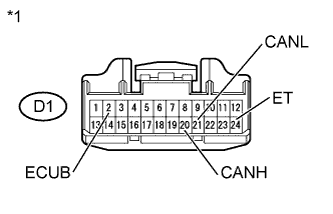
| COMBINATION METER ECU |
Turn the ignition switch off.
Disconnect the D1 combination meter ECU connector.
Measure the resistance according to the value(s) in the table below.
Text in Illustration *1 Front view of wire harness connector
(to Combination Meter ECU)Standard Resistance Terminal No. (Symbol) Wiring Color Switch Condition Specified Condition D1-20 (CANH) - D1-21 (CANL) G - W Ignition switch off 54 to 69 Ω D1-20 (CANH) - D1-24 (ET) G - BR Ignition switch off 200 Ω or higher D1-21 (CANL) - D1-24 (ET) W - BR Ignition switch off 200 Ω or higher D1-20 (CANH) - D1-2 (ECUB) G - L Ignition switch off 6 kΩ or higher D1-21 (CANL) - D1-2 (ECUB) W - L Ignition switch off 6 kΩ or higher
 |
| POWER STEERING ECU |
Turn the ignition switch off.
Disconnect the A19 and D31 power steering ECU connectors.
Measure the resistance according to the value(s) in the table below.
Text in Illustration *1 Rear view of wire harness connector
(to Power Steering ECU)Standard Resistance Terminal No. (Symbol) Wiring Color Switch Condition Specified Condition D31-1 (CANH) - D31-7 (CANL) SB - W Ignition switch off 108 to 132 Ω D31-1 (CANH) - A19-2 (PGND) SB - W-B Ignition switch off 200 Ω or higher D31-7 (CANL) - A19-2 (PGND) W - W-B Ignition switch off 200 Ω or higher D31-1 (CANH) - A19-1 (PIG) SB - W Ignition switch off 6 kΩ or higher D31-7 (CANL) - A19-1 (PIG) W - W Ignition switch off 6 kΩ or higher
 |