Camshaft Oil Control Valve (For Sedan) Installation
INSTALL CAMSHAFT TIMING OIL CONTROL VALVE ASSEMBLY
INSTALL FAN BELT ADJUSTING BAR
INSTALL FAN AND GENERATOR V BELT
ADJUST FAN AND GENERATOR V BELT
INSPECT FAN AND GENERATOR V BELT
CONNECT CABLE TO NEGATIVE BATTERY TERMINAL
CHECK FOR ENGINE OIL LEAKAGE
INSTALL CYLINDER HEAD COVER NO. 2
INSTALL ENGINE UNDER COVER RH
Camshaft Oil Control Valve (For Sedan) -- Installation |
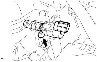
| 1. INSTALL CAMSHAFT TIMING OIL CONTROL VALVE ASSEMBLY |
Apply a light coat of engine oil to a new O-ring and install it onto the camshaft timing oil control valve assembly.
- NOTICE:
- Do not twist the O-ring.
Install the camshaft timing oil control valve assembly with the bolt.
- Torque:
- 7.5 N*m{76 kgf*cm, 66 in.*lbf}
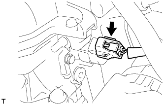
Connect the camshaft timing oil control valve assembly connector.
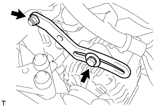
| 2. INSTALL FAN BELT ADJUSTING BAR |
Provisionally install the fan belt adjusting bar with the bolt and nut.
Tighten the nut to the specified torque.
- Torque:
- 11 N*m{112 kgf*cm, 8.1 ft.*lbf}
| 3. INSTALL FAN AND GENERATOR V BELT |
Provisionally install the fan and generator V belt onto each pulley.
- NOTICE:
- Make sure that there is no foreign matter or liquid, such as oil, on the belt and pulleys.
- Make sure that the V belt is securely fitted into the rib grooves of the pulley.
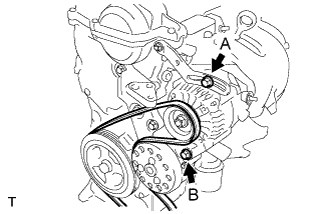
| 4. ADJUST FAN AND GENERATOR V BELT |
Insert an adjusting bar between the engine mounting bracket and generator assembly. Pull the adjusting bar toward the vehicle front to adjust the generator V belt tension (YARIS_NCP93 RM000001DCH00ZX_01_0001.html).
Text in Illustration*a
| OK
|
*b
| NG
|
- NOTICE:
- Do not insert the adjusting bar between the camshaft timing oil control valve assembly and generator assembly. It could damage the camshaft timing oil control valve assembly.
First tighten bolt A, then tighten bolt B.
- Torque:
- 19 N*m{189 kgf*cm, 14 ft.*lbf} for bolt A
- 54 N*m{551 kgf*cm, 40 ft.*lbf} for bolt B
| 5. INSPECT FAN AND GENERATOR V BELT |
Check the belt for wear, cracks or other signs of damage.
If any of the following defects is found, replace the V-ribbed belt.
- HINT:
- The belt is cracked.
- The belt is worn out to the extent that the wires are exposed.
- The belt has chunks missing from the ribbed groves.
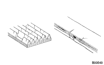
Check that the belt fits properly in the ribbed grooves.
Text in Illustration*a
| CORRECT
|
*b
| INCORRECT
|
- HINT:
- Check with your hand, to confirm that the belt has not slipped out of the grooves on the bottom to the pulley. If it has slipped out, replace the V-ribbed belt. Install a new V-ribbed belt correctly.

|
Inspect the V belt deflection and tension.
Text in Illustration*A
| w/o Air Conditioner
|
*B
| w/ Air Conditioner
|
- Deflection:
Item
| Specified Condition
|
New belt
| 8.0 to 9.0 mm (0.31 to 0.35 in)
|
Used belt
| 12.5 to 13.5 mm (0.49 to 0.53 in)
|
- Tension:
Item
| Specified Condition
|
New belt
| 700 to 800 N (71 to 82 kg, 157 to 180 lb)
|
Used belt
| 300 to 400 N (31 to 41 kg, 67 to 90 lb)
|
If the V belt deflection is not as specified, adjust it.
- HINT:
- When inspecting the V belt deflection, apply 98 N (10 kgf) tensile force to it.
- Perform the V belt inspection and adjustment while the engine is cold.
- V-ribbed belt tension and deflection should be checked immediately after installation of a new belt, and after cranking the engine when inspecting a used belt.
- Check the V belt deflection at the point between the specified pulleys where the deflection is greatest.
- When installing a new belt, set its tension to the intermediate value of the specification.
- When inspecting a belt which has been used for over 5 minutes, apply the Used Belt specifications.
- When reinstalling a belt which has been used for over 5 minutes, adjust its deflection and tension to the intermediate values of each Used Belt specification.
- V-ribbed belt tension and deflection should be checked after 2 revolutions of engine cranking.
- When using a belt tension gauge, confirm its accuracy by using a master gauge first.
| 6. CONNECT CABLE TO NEGATIVE BATTERY TERMINAL |
- Torque:
- 5.4 N*m{55 kgf*cm, 48 in.*lbf}
| 7. CHECK FOR ENGINE OIL LEAKAGE |
| 8. INSTALL CYLINDER HEAD COVER NO. 2 |
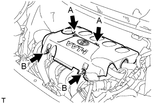
Tighten the 2 A nuts, then the 2 B nuts.
- Torque:
- 7.0 N*m{71 kgf*cm, 62 in.*lbf}
| 9. INSTALL ENGINE UNDER COVER RH |