DESCRIPTION
WIRING DIAGRAM
INSPECTION PROCEDURE
INSPECT FUSE (A/C, HTR SUB1, HTR SUB2)
INSPECT NO. 3 HEATER CONTROL KNOB
CHECK HARNESS AND CONNECTOR (MAIN BODY ECU - AIR CONDITIONING AMPLIFIER)
CHECK HARNESS AND CONNECTOR (No. 3 HEATER CONTROL KNOB - AIR CONDITIONING AMPLIFIER)
INSPECT AIR CONDITIONING AMPLIFIER
INSPECT PTC HEATER RELAY (HTR SUB1, HTR SUB2, HTR SUB3)
CHECK HARNESS AND CONNECTOR (AIR CONDITIONING AMPLIFIER - PTC HEATER RELAY)
CHECK HARNESS AND CONNECTOR (PTC HEATER RELAY - BODY GROUND)
INSPECT PTC HEATER ASSEMBLY
CHECK HARNESS AND CONNECTOR (BATTERY - PTC HEATER RELAY)
CHECK HARNESS AND CONNECTOR (PTC HEATER RELAY - PTC HEATER ASSEMBLY)
AIR CONDITIONING SYSTEM (for Sedan) - PTC Heater Circuit |
DESCRIPTION
PTC heater relays are closed in accordance with signals from the air conditioning amplifier assembly and power is supplied to the PTC heater assembly installed on the radiator heater unit.
WIRING DIAGRAM
INSPECTION PROCEDURE
| 1.INSPECT FUSE (A/C, HTR SUB1, HTR SUB2) |
Remove the A/C fuse from the main body ECU.
Remove the HTR SUB1 and HTR SUB2 fuses from the engine room relay block.
Measure the resistance.
- Standard resistance:
Tester Item
| Specified Condition
|
A/C fuse
| Below 1 Ω
|
HTR SUB 1 fuse
| Below 1 Ω
|
HTR SUB 2 fuse
| Below 1 Ω
|
Reinstall the A/C fuse.
Reinstall the HTR SUB1 and HTR SUB2 fuses.
| 2.INSPECT NO. 3 HEATER CONTROL KNOB |
Remove the No. 3 heater control knob.
Measure the resistance.
- Standard resistance:
Tester Connection
| Condition
| Specified Condition
|
3 (IG+) - 6 (B)
| Max hot position
| Below 1 Ω
|
3 (IG+) - 6 (B)
| Other than max hot position
| 10 kΩ or higher
|
Reinstall the No. 3 heater control knob.
| 3.CHECK HARNESS AND CONNECTOR (MAIN BODY ECU - AIR CONDITIONING AMPLIFIER) |
Disconnect the E6 No. 3 heater control knob connector.
Measure the voltage.
- Standard voltage:
Tester Connection
| Condition
| Specified Condition
|
E6-3 (IG+) - Body ground
| Ignition switch ON
| 11 to 14 V
|
Reconnect the No. 3 heater control knob connector.
| | REPAIR OR REPLACE HARNESS OR CONNECTOR |
|
|
| 4.CHECK HARNESS AND CONNECTOR (No. 3 HEATER CONTROL KNOB - AIR CONDITIONING AMPLIFIER) |
Disconnect the E6 No. 3 heater control knob connector.
Disconnect the E9 air conditioning amplifier connector.
Measure the resistance.
- Standard resistance:
Tester Connection
| Specified Condition
|
E6-6 (B) - E9-14 (HEAT)
| Below 1 Ω
|
Reconnect the No. 3 heater control knob connector.
Reconnect the air conditioning amplifier connector.
| | REPAIR OR REPLACE HARNESS OR CONNECTOR |
|
|
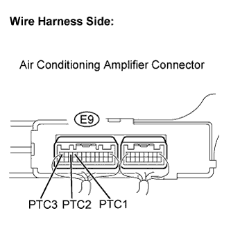
| 5.INSPECT AIR CONDITIONING AMPLIFIER |
Remove the air conditioning amplifier with its connectors still connected.
Turn the ignition switch ON.
When the PTC heater operating conditions are met (engine at idling speed or faster, ambient temperature is 10°C (50°F) or less, engine coolant temperature is 65°C (149°F) or less, and No. 3 heater control knob setting is MAX HOT), turn the blower switch to the Lo setting.
Wait 30 seconds.
Measure the voltage.
- Standard voltage:
Tester Connection
| Specified Condition
|
E9-9 (PTC1) - Body ground
| 11 to 14 V
|
E9-10 (PTC2) - Body ground
| 11 to 14 V
|
E9-12 (PTC3) - Body ground
| 11 to 14 V
|
Reinstall the air conditioning amplifier.
| 6.INSPECT PTC HEATER RELAY (HTR SUB1, HTR SUB2, HTR SUB3) |
Remove the HTR SUB1 relay from the engine room relay block.
Remove the HTR SUB2 and HTR SUB3 relays from the engine room sub relay block.
Measure the resistance.
- Standard resistance:
Tester Connection
| Specified Condition
|
3 - 5
| 10 kΩ or higher
|
3 - 5
| Below 1 Ω
(when battery voltage is applied to terminals 1 and 2)
|
Reinstall the HTR SUB1 relay.
Reinstall the HTR SUB2 and HTR SUB3 relays.
| 7.CHECK HARNESS AND CONNECTOR (AIR CONDITIONING AMPLIFIER - PTC HEATER RELAY) |
Remove the HTR SUB1 relay from the engine room R/B.
Remove the HTR SUB2 and HTR SUB3 relays from the engine room R/B No. 2.
Turn the ignition switch ON.
When the PTC heater operating conditions are met (engine at idling speed or faster, ambient temperature is 10°C (50°F) or less, engine coolant temperature is 65°C (149°F) or less, and No. 3 heater control knob setting is MAX HOT), turn the blower switch to the Lo setting.
Wait 30 seconds.
Measure the voltage.
- Standard voltage.:
Tester Connection
| Specified Condition
|
HTR SUB1-2 - Body ground
| 11 to 14V
|
HTR SUB2-2 - Body ground
| 11 to 14V
|
HTR SUB3-2 - Body ground
| 11 to 14V
|
Reinstall the HTR SUB1 relay.
Reinstall the HTR SUB2 and HTR SUB3 relays.
| | REPAIR OR REPLACE HARNESS OR CONNECTOR |
|
|
| 8.CHECK HARNESS AND CONNECTOR (PTC HEATER RELAY - BODY GROUND) |
Remove the HTR SUB1 relay from the engine room R/B.
Remove the HTR SUB2 and HTR SUB3 relays from the engine room R/B No. 2.
Measure the resistance.
- Standard resistance:
Tester Connection
| Specified Condition
|
HTR SUB1-1 - Body ground
| Below 1 Ω
|
HTR SUB2-1 - Body ground
| Below 1 Ω
|
HTR SUB3-1 - Body ground
| Below 1 Ω
|
Reinstall the HTR SUB1 relay.
Reinstall the HTR SUB2 and HTR SUB3 relays.
| | REPAIR OR REPLACE HARNESS OR CONNECTOR |
|
|
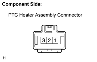
| 9.INSPECT PTC HEATER ASSEMBLY |
Disconnect the A17 PTC heater assembly connector.
Measure the resistance.
- Standard resistance:
Tester Connection
| Specified Condition
|
1 - 2
| Below 1 Ω
|
1 - 3
| Below 1 Ω
|
2 - 3
| Below 1 Ω
|
Reconnect the PTC heater assembly connector.
| | REPLACE PTC HEATER ASSEMBLY |
|
|
| 10.CHECK HARNESS AND CONNECTOR (BATTERY - PTC HEATER RELAY) |
Remove the HTR SUB1 relay from the engine room R/B.
Remove the HTR SUB2 and HTR SUB3 relays from the engine room R/B No. 2.
Measure the voltage.
- Standard voltage:
Tester Connection
| Condition
| Specified Condition
|
HTR SUB1-5 - Body ground
| Always
| 11 to 14 V
|
HTR SUB2-5 - Body ground
| Always
| 11 to 14 V
|
HTR SUB3-5 - Body ground
| Always
| 11 to 14 V
|
Reinstall the HTR SUB1 relay.
Reinstall the HTR SUB2 and HTR SUB3 relays.
| | REPAIR OR REPLACE HARNESS OR CONNECTOR |
|
|
| 11.CHECK HARNESS AND CONNECTOR (PTC HEATER RELAY - PTC HEATER ASSEMBLY) |
Remove the HTR SUB1 relay from the engine room R/B.
Remove the HTR SUB2 and HTR SUB3 relays from the engine room R/B No. 2.
Disconnect the A17 PTC heater assembly connector.
Measure the resistance.
- Standard resistance:
Tester Connection
| Specified Condition
|
HTR SUB1-3 - A17-2 (B)
| Below 1 Ω
|
HTR SUB2-3 - A17-3 (B)
| Below 1 Ω
|
HTR SUB3-3 - A17-1 (B)
| Below 1 Ω
|
Reinstall the HTR SUB1 relay.
Reinstall the HTR SUB2 and HTR SUB3 relays.
Reconnect the PTC heater assembly connector.
| | REPAIR OR REPLACE HARNESS OR CONNECTOR |
|
|