Dtc C1552/52 Pig Power Source Circuit
DESCRIPTION
WIRING DIAGRAM
INSPECTION PROCEDURE
READ VALUE USING TECHSTREAM
INSPECT FUSE (EPS FUSE)
CHECK HARNESS AND CONNECTOR (POWER STEERING ECU - BODY GROUND)
INSPECT STEERING COLUMN ASSEMBLY (POWER STEERING MOTOR)
DTC C1552/52 PIG Power Source Circuit |
DTC C1553/53 When Resetting Voltage, Vehicle is Being Driven |
DTC C1554/54 EPS Relay Circuit |
DTC C1555/55 EPS Motor Relay Circuit |
DESCRIPTION
When a problem occurs in the system, the power source relay circuit and the motor relay circuit are shut off to stop the power assist. The ECU must be replaced when there is a problem with the relays because each relay is built into the ECU.DTC No.
| DTC Detection Condition
| Trouble Area
|
C1552/52
| PIG power source circuit malfunction
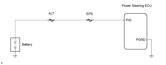
| - EPS fuse
- PIG power source circuit
- Power steering ECU
|
C1553/53
| Abnormal overvoltage
| - IG and PIG power source circuit
- Power steering ECU
|
C1554/54
| Power source relay circuit malfunction
| - EPS fuse
- PIG power source circuit
- Power steering ECU
|
C1555/55
| Motor relay circuit malfunction
| - Power steering ECU
|
WIRING DIAGRAM
INSPECTION PROCEDURE
| 1.READ VALUE USING TECHSTREAM |
Connect a Techstream to the DLC3.
Turn the ignition switch to ON.
Turn the Techstream on.
Enter the following menus: Chassis / EMPS / Data List.
Select the item "PIG Power Supply" in the Data List and read the value displayed on the Techstream.
EMPS:Tester Display
| Measurement Item/Range
| Normal Condition
| Diagnostic Note
|
PIG Power Supply
| Power source voltage to activate motor: Minimum: 0.0000 V, Maximum: 20.1531 V
| 11 to 14 V: Always
| -
|
- OK:
- The normal condition value is displayed on the Techstream.
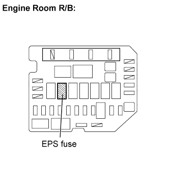
| 2.INSPECT FUSE (EPS FUSE) |
Remove the EPS fuse from the engine room R/B.
Measure the resistance of the fuse.
- Standard resistance:
- Below 1Ω
| | INSPECT SHORT CIRCUIT IN COMPONENTS AND WIRES CONNECTED TO FUSE |
|
|
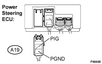
| 3.CHECK HARNESS AND CONNECTOR (POWER STEERING ECU - BODY GROUND) |
Disconnect the connector from the power steering ECU.
Measure the voltage and the resistance.
- Standard:
Tester Connection
| Condition
| Specified Condition
|
PIG (A19-1) - Body ground
| Always
| 11 to 14 V
|
PGND (A19-2) - Body ground
| Always
| Below 1 Ω
|
| | REPAIR OR REPLACE HARNESS OR CONNECTOR |
|
|
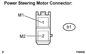
| 4.INSPECT STEERING COLUMN ASSEMBLY (POWER STEERING MOTOR) |
Disconnect the connector from the power steering ECU.
Measure the resistance.
- Standard resistance:
Tester Connection
| Condition
| Specified Condition
|
M1 (b1-1) - M2 (b1-2)
| Always
| 0.08 to 0.15 Ω
|
M1 (b1-1) - Body ground
| Always
| 1 MΩ or higher
|
M2 (b1-2) - Body ground
| Always
| 1 MΩ or higher
|