Dtc C1551/51 Ig Power Supply Voltage Malfunction
DESCRIPTION
WIRING DIAGRAM
INSPECTION PROCEDURE
READ VALUE USING TECHSTREAM
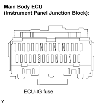
INSPECT FUSE (ECU-IG)
CHECK HARNESS AND CONNECTOR (POWER STEERING ECU - BODY GROUND)
DTC C1551/51 IG Power Supply Voltage Malfunction |
DESCRIPTION
The power steering ECU distinguishes the ignition switch status as on or off through the IG power source circuit.DTC No.
| DTC Detection Condition
| Trouble Area
|
C1551/51
| Open or short in IG power source circuit with ignition switch on.
| - ECU-IG fuse
- IG power source circuit
- Power steering ECU
|
WIRING DIAGRAM
INSPECTION PROCEDURE
| 1.READ VALUE USING TECHSTREAM |
Connect a Techstream to the DLC3.
Turn the ignition switch to ON.
Turn the Techstream on.
Enter the following menus: Chassis / EMPS / Data List.
Select the item "IG Power Supply" in the Data List and read the value displayed on the Techstream.
EMPS:Tester Display
| Measurement Item/Range
| Normal Condition
| Diagnostic Note
|
IG Power Supply
| ECU power source voltage: Minimum: 0.0000 V, Maximum: 20.1531 V
| 11 to 14 V: Ignition switch ON
| -
|
- OK:
- The normal condition value is displayed on the Techstream.
Remove the ECU-IG fuse from the instrument panel J/B.
Check the resistance of the fuse.
- Standard resistance:
- Below 1 Ω
| | INSPECT SHORT CIRCUIT IN COMPONENTS AND WIRES CONNECTED TO FUSE |
|
|
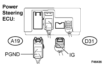
| 3.CHECK HARNESS AND CONNECTOR (POWER STEERING ECU - BODY GROUND) |
Disconnect the connectors from the power steering ECU.
Measure the voltage and the resistance.
- Standard:
Tester Connection
| Condition
| Specified Condition
|
IG (D31-6) - Body ground
| Ignition switch on
| 11 to 14 V
|
PGND (A19-2) - Body ground
| Always
| Below 1 Ω
|
| | REPAIR OR REPLACE HARNESS OR CONNECTOR |
|
|