Dtc C1541/41 Speed Sensor Malfunction
DESCRIPTION
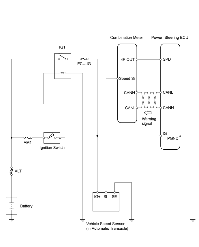
WIRING DIAGRAM
INSPECTION PROCEDURE
READ VALUE USING TECHSTREAM
CHECK HARNESS AND CONNECTOR (POWER STEERING ECU - COMBINATION METER)
DTC C1541/41 Speed Sensor Malfunction |
DTC C1542/42 Speed Sensor Malfunction |
DTC C1571/71 Speed Sensor Malfunction (Test Mode DTC) |
DESCRIPTION
Based on the vehicle speed signal received from the combination meter, the power steering ECU adjusts the amount of power assist according to vehicle speed. The power steering ECU monitors the speed signal input and stores a DTC if a malfunction is detected. While a malfunction exists in the vehicle speed signal, fail-safe operation maintains the amount of power assist at the level for a speed of 70 km/h (43 mph).- NOTICE:
- Revving the engine while the vehicle is stopped may cause DTC C1541/41 or C1542/42 to be stored.
- HINT:
- If C1541/41 is stored while the vehicle is stopped, driving the vehicle for 5 minutes or more and then turning the ignition switch to off will clear the DTC.
- If C1542/42 is stored while the vehicle is stopped, driving the vehicle for 5 minutes or more will clear the DTC.
- These DTCs are only for vehicles without a skid control ECU (ABS ECU).
- When the sensor is normal, a pulse signal (43 Hz at 37 mph [60 km/h]) that alternates between 0 V and 5 V is transmitted to the ECU.
DTC No.
| Detection Item
| Trouble Area
|
C1541/41
| Vehicle Speed Signal Abnormal Increase
| - Speed sensor
- Speed sensor circuit
- Combination meter
- Power steering ECU
|
While vehicle stopped, engine rpm exceeds threshold* for 300 seconds or more, cumulative.
| -
|
C1542/42
| Vehicle Speed Signal Abnormal Decrease
| - Speed sensor
- Speed sensor circuit
- Combination meter
- Power steering ECU
|
While vehicle stopped, engine rpm exceeds threshold* for 30 seconds or more, cumulative.
| -
|
C1571/71
| Speed sensor malfunction (Test mode).
| - Speed sensor
- Speed sensor circuit
- Combination meter
- Power steering ECU
|
*Threshold: An engine speed of 4000 rpm or greater is detected within 5 minutes after engine is started, or an engine speed of 2100 rpm or greater is detected 5 minutes or more after engine is started.
WIRING DIAGRAM
INSPECTION PROCEDURE
- HINT:
- Confirm that DTC C1571/71 has been cleared by activating test mode after the repair is completed.
| 1.READ VALUE USING TECHSTREAM |
Connect a Techstream to the DLC3.
Turn the ignition switch to ON.
Turn the Techstream on.
Enter the following menus: Chassis / EMPS /Data List.
Select the item "Meter Vehicle Velocity" in the Data List and the value displayed on the Techstream.
EMPSTester Display
| Measurement Item/Range
| Normal Condition
| Diagnostic Note
|
Meter Vehicle Velocity
| Vehicle speed from meter:
Minimum: 0 mph (km/h),
Maximum: 158.5 mph (255 km/h)
| Vehicle driven at constant speed
| -
|
- OK:
- When the vehicle is being driven at 12.4 mph (20 km/h) the Techstream displays a speed within the range of 11.1 to 13.6 mph (18 to 22 km/h).
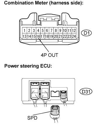
| 2.CHECK HARNESS AND CONNECTOR (POWER STEERING ECU - COMBINATION METER) |
Disconnect the connectors from the power steering ECU and the combination meter.
Measure the resistance.
- Standard resistance:
Tester Connection
| Condition
| Specified Condition
|
SPD (D31-5) - 4P OUT (D1-16)
| Always
| Below 1 Ω
|
SPD (D31-5) - Body ground
| Always
| 10 kΩ or higher
|
| | REPAIR OR REPLACE HARNESS OR CONNECTOR |
|
|