Brake Pedal (For Sedan) -- Installation |
| 1. INSTALL BRAKE PEDAL PAD |
Install the brake pedal pad onto the brake pedal.
| 2. INSTALL BRAKE PEDAL BUSH |
Apply lithium soap base glycol grease to the 2 bushes.
Install the 2 bushes onto the brake pedal.
| 3. INSTALL BRAKE PEDAL |
Install the brake pedal onto the pedal support with the brake pedal shaft and nut.
- Torque:
- 37 N*m{375 kgf*cm, 27 ft.*lbf}
| 4. INSTALL BRAKE PEDAL SUPPORT |
 |
Install the pedal support with the bolt and 4 nuts.
- Torque:
- Bolt:
- 24 N*m{241 kgf*cm, 17 ft.*lbf}
- Nut:
- 9.0 N*m{92 kgf*cm, 80 in.*lbf}
| 5. INSTALL BRAKE MASTER CYLINDER PUSH ROD CLEVIS |
Apply lithium soap base glycol grease to the push rod pin.
Install the push rod clevis with the push rod pin and clip.
 |
Install the brake pedal return spring.
| 6. INSTALL STOP LIGHT SWITCH MOUNTING ADJUSTER |
 |
Install a new stop light switch mounting adjuster onto the pedal support.
| 7. INSTALL STOP LIGHT SWITCH |
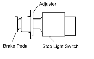 |
Insert the stop light switch into the adjuster until it just touches the brake pedal.
- NOTICE:
- Do not depress the brake pedal.
Make a quarter turn clockwise to install the stop light switch.
- NOTICE:
- Do not depress the brake pedal.
- HINT:
- The turning torque for installing the stop light switch:
- Torque:
- 1.5 N*m{15 kgf*cm, 13 in.*lbf} or less
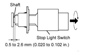 |
Check the stop light switch clearance.
- Stop light switch clearance:
- 0.5 to 2.6 mm (0.020 to 0.102 in.)
Connect the wire harness clamp onto the pedal support.
Connect the connector to the stop light switch.
| 8. INSPECT AND ADJUST BRAKE PEDAL |
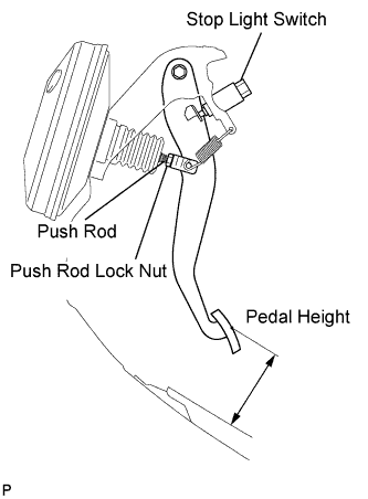 |
Inspect the brake pedal height.
- Pedal height from floor:
w/ ABS w/o ABS 113.1 to 123.1 mm
(4.45 to 4.85 in.)107.8 to 117.8 mm
(4.244 to 4.638 in.)
Adjust the brake pedal height.
Disconnect the connector from the stop light switch.
Turn the stop light switch counterclockwise, and remove the stop light switch.
Loosen the push rod lock nut.
Adjust the pedal height by turning the pedal push rod.
- Pedal height from floor:
w/ ABS w/o ABS 113.1 to 123.1 mm
(4.45 to 4.85 in.)107.8 to 117.8 mm
(4.244 to 4.638 in.)
Tighten the push rod lock nut.
- Torque:
- 26 N*m{265 kgf*cm, 19 ft.*lbf}
Insert the stop light switch into the adjuster until it just touches the brake pedal.
- NOTICE:
- Do not depress the brake pedal.
Make a quarter turn clockwise to install the stop light switch.
- NOTICE:
- Do not depress the brake pedal.
- HINT:
- The turning torque for installing the stop light switch:
- Torque:
- 1.5 N*m{15 kgf*cm, 13 in.*lbf}or less
Check the stop light switch clearance.
- Stop light switch clearance:
- 0.5 to 2.6 mm (0.020 to 0.102 in.)
Connect the connector to the stop light switch.
Inspect the brake pedal free play.
Stop the engine and depress the brake pedal several times until there is no vacuum left in the booster.
Push in the pedal until the beginning of the resistance is felt. Measure the distance as shown.
- Pedal free play:
- 1.0 to 6.0 mm (0.039 to 0.236 in.)
 |
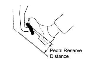
Inspect the brake pedal reserve distance.
Release the parking brake lever. With the engine running, depress the pedal and measure the pedal reserve distance as shown.
- Pedal reserve distance from floor at 294 N (30 kgf, 66.1 lbf):
for ABS with VSC for ABS without VSC w/o ABS More than 76 mm (2.99 in.) More than 73 mm (2.87 in.) More than 70 mm (2.75 in.)
- HINT:
- Sound and resistance from the brake booster when the brake pedal is depressed without a vacuum does not indicate a problem.
 |
| 9. INSTALL STEERING INTERMEDIATE SHAFT ASSEMBLY |
Connect all the connectors and clamp the wire harnesses onto the steering column assembly bracket.
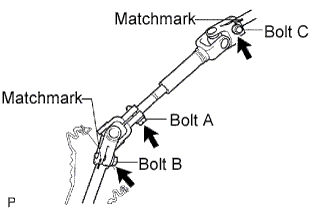 |
Align the matchmarks on steering intermediate shaft assembly No. 2 and the steering sliding yoke and provisionally install them with bolt C.
- Torque:
- 35 N*m{360 kgf*cm, 26 ft.*lbf}
Align the matchmarks on the steering sliding yoke and steering gear assembly and install them with bolt B.
- Torque:
- 35 N*m{360 kgf*cm, 26 ft.*lbf}
Tighten bolt A.
- Torque:
- 35 N*m{360 kgf*cm, 26 ft.*lbf}
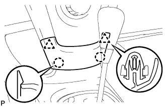
| 10. INSTALL COLUMN HOLE COVER SILENCER SHEET |
Install the column hole cover plate with the 2 clips.
 |
Install the floor carpet.
| 11. INSTALL LOWER INSTRUMENT PANEL FINISH PANEL SUB-ASSEMBLY |
| 12. INSTALL INSTRUMENT PANEL UNDER COVER SUB-ASSEMBLY |
| 13. INSTALL UPPER INSTRUMENT PANEL SUB-ASSEMBLY |
| 14. INSTALL GLOVE COMPARTMENT DOOR ASSEMBLY |
| 15. INSTALL FRONT PILLAR GARNISH RH |
| 16. INSTALL FRONT PILLAR GARNISH LH |
| 17. INSTALL FRONT DOOR OPENING TRIM WEATHERSTRIP RH |
| 18. INSTALL FRONT DOOR OPENING TRIM WEATHERSTRIP LH |
| 19. INSTALL COMBINATION METER ASSEMBLY |
| 20. INSTALL INSTRUMENT CLUSTER FINISH PANEL NO.1 |
| 21. INSTALL INSTRUMENT PANEL FINISH PANEL END RH |
| 22. INSTALL INSTRUMENT PANEL FINISH PANEL END LH |
| 23. INSTALL CENTER LOWER INSTRUMENT PANEL FINISH PANEL |
 |
Engage the 2 claws and 2 clips and install the instrument panel finish panel lower center.
| 24. CONNECT CABLE TO NEGATIVE BATTERY TERMINAL |
- Torque:
- 5.4 N*m{55 kgf*cm, 48 in.*lbf}
| 25. INSPECT SRS WARNING LIGHT |