Manual Transaxle Assembly (For Sedan) Installation
INSTALL MANUAL TRANSAXLE ASSEMBLY
INSTALL TRANSVERSE ENGINE ENGINE MOUNTING BRACKET
INSTALL TRANSVERSE ENGINE ENGINE MOUNTING INSULATOR
INSTALL TRANSVERSE ENGINE ENGINE MOUNTING CONTROL BRACKET
INSTALL FRONT SUSPENSION CROSSMEMBER SUB-ASSEMBLY
INSTALL FRONT DRIVE SHAFT ASSEMBLY LH
INSTALL FRONT DRIVE SHAFT ASSEMBLY RH
INSTALL FRONT AXLE ASSEMBLY LH
INSTALL FRONT AXLE ASSEMBLY RH
INSTALL FRONT LOWER NO. 1 SUSPENSION ARM SUB-ASSEMBLY LH
INSTALL FRONT LOWER NO. 1 SUSPENSION ARM SUB-ASSEMBLY RH
INSTALL TIE ROD END SUB-ASSEMBLY LH
INSTALL TIE ROD END SUB-ASSEMBLY RH
INSTALL FRONT STABILIZER LINK ASSEMBLY LH
INSTALL FRONT STABILIZER LINK ASSEMBLY RH
INSTALL SPEED SENSOR FRONT LH (w/ ABS)
INSTALL SPEED SENSOR FRONT RH (w/ ABS)
INSTALL FRONT AXLE SHAFT LH NUT
INSTALL FRONT AXLE SHAFT RH NUT
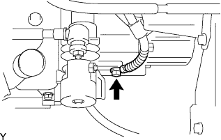
INSTALL STARTER ASSEMBLY
CONNECT CONNECTOR
CONNECT WIRE HARNESS
INSTALL CONTROL CABLE BRACKET
CONNECT TRANSMISSION CONTROL CABLE ASSEMBLY
INSTALL CLUTCH RELEASE CYLINDER ASSEMBLY
INSTALL BATTERY CARRIER
INSTALL BATTERY TRAY
INSTALL BATTERY
INSTALL BATTERY CLAMP SUB-ASSEMBLY
INSTALL AIR CLEANER BRACKET
INSTALL AIR CLEANER ASSEMBLY
INSTALL NO. 2 CYLINDER HEAD COVER
INSTALL COWL TOP PANEL OUTER
INSTALL FRONT AIR SHUTTER SEAL
INSTALL WINDSHIELD WIPER MOTOR AND LINK
INSTALL COWL TOP VENTILATOR LOUVER SUB-ASSEMBLY
INSTALL COWL SIDE VENTILATOR SUB-ASSEMBLY RH
INSTALL COWL SIDE VENTILATOR SUB-ASSEMBLY LH
INSTALL FRONT WIPER ARM AND BLADE ASSEMBLY LH
INSTALL FRONT WIPER ARM AND BLADE ASSEMBLY RH
INSTALL FRONT WIPER ARM HEAD CAP
INSTALL HOOD SUB-ASSEMBLY
INSPECT HOOD SUB-ASSEMBLY
ADJUST HOOD SUB-ASSEMBLY
ADD TRANSAXLE OIL
INSPECT AND ADJUST TRANSAXLE OIL
INSTALL ENGINE UNDER COVER RH
INSTALL ENGINE UNDER COVER LH
INSTALL FRONT WHEELS
INSTALL STEERING SLIDING YOKE SUB-ASSEMBLY
INSTALL COLUMN HOLE COVER SILENCER SHEET
INSPECT ABS SPEED SENSOR SIGNAL (w/ ABS)
INSPECT AND ADJUST FRONT WHEEL ALIGNMENT
INSPECT FOR EXHAUST GAS LEAK
INSPECT FOR TRANSAXLE OIL LEAK
Manual Transaxle Assembly (For Sedan) -- Installation |
| 1. INSTALL MANUAL TRANSAXLE ASSEMBLY |
Align the input shaft with the clutch disc and install the manual transaxle onto the engine.
Install the 7 bolts.
- Torque:
- 33 N*m{336 kgf*cm, 24 ft.*lbf}
| 2. INSTALL TRANSVERSE ENGINE ENGINE MOUNTING BRACKET |
Install the engine mounting bracket LH with the 4 bolts.
- Torque:
- 64 N*m{653 kgf*cm, 47 ft.*lbf}
| 3. INSTALL TRANSVERSE ENGINE ENGINE MOUNTING INSULATOR |
Install the engine mounting insulator LH with the 5 bolts.
- Torque:
- 52 N*m{530 kgf*cm, 38 ft.*lbf}
Install the engine mounting bracket LH and engine mounting insulator LH with the bolt and nut.
- Torque:
- 52 N*m{530 kgf*cm, 38 ft.*lbf}
| 4. INSTALL TRANSVERSE ENGINE ENGINE MOUNTING CONTROL BRACKET |
Install the engine mounting control bracket with the 4 bolts.
- Torque:
- 39 N*m{398 kgf*cm, 29 ft.*lbf}
| 5. INSTALL FRONT SUSPENSION CROSSMEMBER SUB-ASSEMBLY |
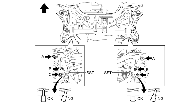
Place wooden blocks or plate lift attachments on an engine lifter, and then set the front suspension crossmember sub-assembly so that the attachments are in the positions shown in the illustration.
Text in Illustration
| Front of the Vehicle
|

| Attachment Placement Positions
|
Provisionally install the front suspension crossmember onto the body with the 6 bolts.
By inserting SST into the datum holes in the front suspension crossmembers RH and LH alternately, tighten bolts A, B and C on both sides to the specified torque, in several steps.
- SST
- 09670-00011
- Torque:
- Bolt A:
- 87 N*m{887 kgf*cm, 64 ft.*lbf}
- Bolt B:
- 151 N*m{1540 kgf*cm, 111 ft.*lbf}
- Bolt C:
- 98 N*m{999 kgf*cm, 72 ft.*lbf}
- NOTICE:
- Insert SST into the datum hole in a vertical orientation.
- If SST cannot be inserted into the datum hole vertically, loosen all the bolts and then insert SST again.
Text in Illustration*a
| Datum Hole
| -
| -
|
| Front of the Vehicle
| -
| -
|
Install the engine moving control rod with the bolt.
- Torque:
- 120 N*m{1224 kgf*cm, 89 ft.*lbf}
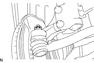
| 6. INSTALL FRONT DRIVE SHAFT ASSEMBLY LH |
for Automatic Transaxle:
Coat the spline of the inboard joint with ATF.
for Manual Transaxle:
Coat the spline of the inboard joint with gear oil.
Align the inboard joint splines and install the drive shaft with a screwdriver and hammer.
- NOTICE:
- Face the cut area of the front drive inboard joint hole snap ring downward.
- Do not damage the oil seal.
- Do not damage the inboard joint boot.
- HINT:
- Confirm whether the drive shaft is securely driven in by checking the reaction force and sound.
| 7. INSTALL FRONT DRIVE SHAFT ASSEMBLY RH |
- HINT:
- The installation procedure for the RH side is the same as that for the LH side.
| 8. INSTALL FRONT AXLE ASSEMBLY LH |
Push the front axle out of the vehicle to align the spline of the drive shaft with the front axle and insert the front axle.
- NOTICE:
- Do not push the front axle further out of the vehicle than is necessary.
- Do not damage the outboard joint boot.
- Check for any foreign matter on the speed sensor rotor and insertion part.
- Do not damage the speed sensor rotor.
| 9. INSTALL FRONT AXLE ASSEMBLY RH |
- HINT:
- The installation procedure for the RH side is the same as that for the LH side.
| 10. INSTALL FRONT LOWER NO. 1 SUSPENSION ARM SUB-ASSEMBLY LH |
Install the lower arm onto the steering knuckle with a new castle nut.
- Torque:
- 98 N*m{1,000 kgf*cm, 72 ft.*lbf}
- NOTICE:
- If the holes for the clip are not aligned, tighten the nut by a further turn of up to 60°.
Install a new clip.
| 11. INSTALL FRONT LOWER NO. 1 SUSPENSION ARM SUB-ASSEMBLY RH |
- HINT:
- The installation procedure for the RH side is the same as that for the LH side.
| 12. INSTALL TIE ROD END SUB-ASSEMBLY LH |
Install the tie rod end onto the steering knuckle with a new castle nut.
- Torque:
- 49 N*m{500 kgf*cm, 36 ft.*lbf}
- NOTICE:
- If the holes for the clip are not aligned, tighten the nut by a further turn of up to 60°.
Install a new cotter pin.
| 13. INSTALL TIE ROD END SUB-ASSEMBLY RH |
- HINT:
- The installation procedure for the RH side is the same as that for the LH side.
| 14. INSTALL FRONT STABILIZER LINK ASSEMBLY LH |
Install the stabilizer link with the nut.
- Torque:
- 74 N*m{755 kgf*cm, 55 ft.*lbf}
- HINT:
- If the ball joint turns together with the nut, use a socket hexagon wrench 6 to hold the stud.
| 15. INSTALL FRONT STABILIZER LINK ASSEMBLY RH |
- HINT:
- The installation procedure for the RH side is the same as that for the LH side.
| 16. INSTALL SPEED SENSOR FRONT LH (w/ ABS) |
Install the speed sensor onto the steering knuckle with the bolt.
- Torque:
- 8.5 N*m{87 kgf*cm, 75 in.*lbf}
- NOTICE:
- Check that the speed sensor tip and installation portion are free of foreign matter.
- Install the speed sensor without turning it from its original installation angle.
Install the flexible hose and speed sensor with the bolt.
- Torque:
- 29 N*m{300 kgf*cm, 22 ft.*lbf}
- NOTICE:
- Install the flexible hose and speed sensor without twisting them.
| 17. INSTALL SPEED SENSOR FRONT RH (w/ ABS) |
- HINT:
- The installation procedure for the RH side is the same as that for the LH side.
| 18. INSTALL FRONT AXLE SHAFT LH NUT |
Using a 30 mm socket wrench, install a new axle hub nut.
- Torque:
- 216 N*m{2,203 kgf*cm, 160 ft.*lbf}
Using a chisel and hammer, caulk the axle hub nut.
| 19. INSTALL FRONT AXLE SHAFT RH NUT |
- HINT:
- The installation procedure for the RH side is the same as that for the LH side.
| 20. INSTALL STARTER ASSEMBLY |
Install the starter assembly with the 2 bolts.
- Torque:
- 37 N*m{377 kgf*cm, 27 ft.*lbf}
Connect the connector.
Connect terminal 30 with the nut.
- Torque:
- 9.8 N*m{100 kgf*cm, 87 in.*lbf}
Close the terminal cap.
Connect the back-up light switch connector.
Connect the wire harness with the bolt.
- Torque:
- 26 N*m{260 kgf*cm, 19 ft.*lbf}
| 23. INSTALL CONTROL CABLE BRACKET |
Install the control cable bracket with the 2 bolts.
- Torque:
- 25 N*m{250 kgf*cm, 18 ft.*lbf}
| 24. CONNECT TRANSMISSION CONTROL CABLE ASSEMBLY |
Connect the 2 cable ends and install the 2 washers and the 2 clips.
Install 2 new clips onto the control cable bracket.
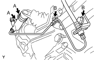
| 25. INSTALL CLUTCH RELEASE CYLINDER ASSEMBLY |
Install the clutch release cylinder and clutch pipe with the 4 bolts.
- Torque:
- 12 N*m{120 kgf*cm, 8.7 ft.*lbf} for bolt A
- 12 N*m{122 kgf*cm, 8.9 ft.*lbf} for bolt B
| 26. INSTALL BATTERY CARRIER |
Install the battery carrier with the 5 bolts.
- Torque:
- 17 N*m{175 kgf*cm, 13 ft.*lbf}
| 29. INSTALL BATTERY CLAMP SUB-ASSEMBLY |
| 30. INSTALL AIR CLEANER BRACKET |
Install the air cleaner bracket with the 2 bolts.
- Torque:
- 19 N*m{194 kgf*cm, 14 ft.*lbf}
| 31. INSTALL AIR CLEANER ASSEMBLY |
Install the air cleaner case with air cleaner inlet No. 1 with the 2 bolts.
- Torque:
- 7.8 N*m{80 kgf*cm, 69 in.*lbf}
Connect the wire harness to the air cleaner case.
Install the air cleaner element.
Install and lock the air cleaner cap and the air cleaner hose and then tighten the air cleaner hose clamp.
- Torque:
- 4.0 N*m{41 kgf*cm, 35 in.*lbf}
Connect the ventilation hose to the air cleaner hose.
Connect the vacuum switching valve connector and the wire harness clamp.
Connect the fuel vapor feed hose to the vacuum switching valve assembly and air cleaner hose.
Connect the intake air flow meter connector and the wire harness clamp.
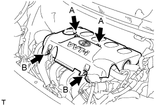
| 32. INSTALL NO. 2 CYLINDER HEAD COVER |
Tighten the 2 A nuts, then the 2 B nuts.
- Torque:
- 7.0 N*m{71 kgf*cm, 62 in.*lbf}
| 33. INSTALL COWL TOP PANEL OUTER |
Install the cowl top panel outer with the 8 bolts.
- Torque:
- 6.5 N*m{66 kgf*cm, 58 in.*lbf}
Install the cowl top to cowl inner brace with the 2 bolts.
- Torque:
- 6.5 N*m{66 kgf*cm, 58 in.*lbf}
Connect the wire harness clamp.
| 34. INSTALL FRONT AIR SHUTTER SEAL |
Engage the 3 claws to install the front air shutter seal RH.
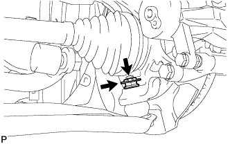
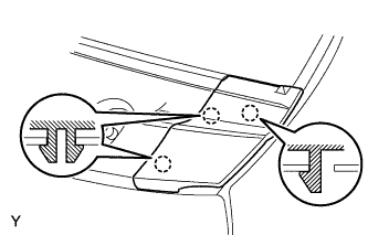
| 35. INSTALL WINDSHIELD WIPER MOTOR AND LINK |
Connect the connector.
Slide the wiper link as shown in the illustration and engage the rubber pin with the body.
Install the front wiper motor and link with the 2 bolts.
- Torque:
- 5.5 N*m{56 kgf*cm, 49 in.*lbf}
| 36. INSTALL COWL TOP VENTILATOR LOUVER SUB-ASSEMBLY |
Connect the washer hoses.
Engage the 5 hooks.
Engage the 8 hooks and the 4 claws.
Install the cowl top ventilator louver sub-assembly with the 3 clips.
| 37. INSTALL COWL SIDE VENTILATOR SUB-ASSEMBLY RH |
- HINT:
- Use the same procedure as for the LH side.
| 38. INSTALL COWL SIDE VENTILATOR SUB-ASSEMBLY LH |
Engage the 3 claws and install the cowl side ventilator sub-assembly LH.
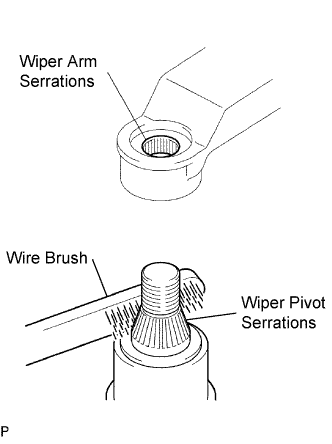
| 39. INSTALL FRONT WIPER ARM AND BLADE ASSEMBLY LH |
Scrape any metal powder off the serrated part of the wiper arm with a round file or the equivalent (when reinstalling).
Clean the wiper pivot serrations with a wire brush.
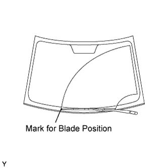
Operate the wiper, then stop the windshield wiper motor in the automatic stop position.
Align the blade tip with the mark on the windshield glass, as shown in the illustration.
Tighten the nut of the front wiper arm.
- Torque:
- 26 N*m{265 kgf*cm, 19 ft.*lbf}
| 40. INSTALL FRONT WIPER ARM AND BLADE ASSEMBLY RH |
Scrape any metal powder off the serrated part of the wiper arm with a round file or the equivalent (when reinstalling).
Clean the wiper pivot serrations with a wire brush.
Operate the wiper, then stop the windshield wiper motor in the automatic stop position.
Align the blade tip with the mark on the windshield glass, as shown in the illustration.
Tighten the nut of the front wiper arm.
- Torque:
- 26 N*m{265 kgf*cm, 19 ft.*lbf}
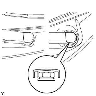
| 41. INSTALL FRONT WIPER ARM HEAD CAP |
Engage the claw and install the 2 front wiper arm head caps.
| 42. INSTALL HOOD SUB-ASSEMBLY |
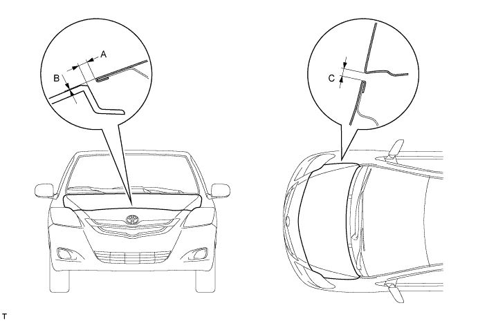
| 43. INSPECT HOOD SUB-ASSEMBLY |
Check that the clearance measurements are within the standard ranges.
- Standard:
Area
| Measurement
| Area
| Measurement
|
A
| 2.35 to 6.35 mm
(0.092 to 0.250 in.)
| C
| 2.0 to 5.0 mm
(0.079 to 0.197 in.)
|
B
| -2 to 2 mm
(-0.079 to 0.079 in.)
| -
| -
|
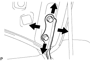
| 44. ADJUST HOOD SUB-ASSEMBLY |
Loosen the hood side hinge bolts.
Move the hood to adjust the clearance to within the standard range.
Tighten the hood side hinge bolts after the adjustment.
- Torque:
- 13 N*m{133 kgf*cm, 10 ft.*lbf}
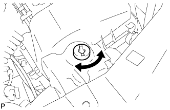
Adjust the height of the hood front end by turning the cushion rubber.
- HINT:
- The cushion rubber can be raised and lowered by turning it.
Adjust the hood lock.
Loosen the 3 bolts.
Adjust the hood lock position so that the striker can enter it smoothly.
Tighten the 3 bolts after the adjustment.
- Torque:
- 7.5 N*m{76 kgf*cm, 66 in.*lbf}
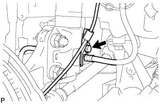
| 46. INSPECT AND ADJUST TRANSAXLE OIL |
Text in Illustration*a
| 0 to 5 mm (0 to 0.196 in.)
|
Stop the vehicle in a level place.
Remove the transmission filler plug and the gasket.
Check that the oil surface is within 5 mm (0.20 in.) of the bottom of the transmission filler plug opening.
- NOTICE:
- Excessively large or small amounts of oil may cause problems.
- After replacing the oil, drive the vehicle and check the oil level again.
Check for oil leakage when the oil level is low.
Install the transmission filler plug and a new gasket.
- Torque:
- 39 N*m{400 kgf*cm, 29 ft.*lbf}
| 47. INSTALL ENGINE UNDER COVER RH |
| 48. INSTALL ENGINE UNDER COVER LH |
- Torque:
- 103 N*m{1050 kgf*cm, 76 ft.*lbf}
| 50. INSTALL STEERING SLIDING YOKE SUB-ASSEMBLY |
Align the matchmarks and install the sliding yoke onto the intermediate shaft with bolt B.
Text in Illustration*1
| Bolt A
|
*2
| Bolt B
|
*a
| Matchmark
|
- Torque:
- 35 N*m{360 kgf*cm, 26 ft.*lbf}
Tighten bolt A.
- Torque:
- 35 N*m{360 kgf*cm, 26 ft.*lbf}
| 51. INSTALL COLUMN HOLE COVER SILENCER SHEET |
Install the column hole cover silencer sheet with the 2 clips.
Install the floor carpet.
| 52. INSPECT ABS SPEED SENSOR SIGNAL (w/ ABS) |
(YARIS_NCP93 RM000000XHT08HX.html)
| 53. INSPECT AND ADJUST FRONT WHEEL ALIGNMENT |
(YARIS_NCP93 RM000001BCN01PX.html)
| 54. INSPECT FOR EXHAUST GAS LEAK |
| 55. INSPECT FOR TRANSAXLE OIL LEAK |