Power Steering System (For Sedan) Ts And Cg Terminal Circuit
DESCRIPTION
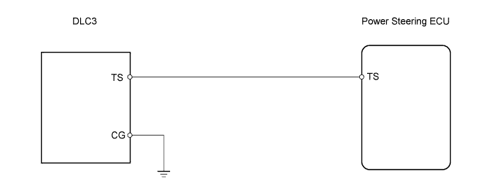
WIRING DIAGRAM
INSPECTION PROCEDURE
INSPECT DLC3 TERMINAL VOLTAGE
CHECK HARNESS AND CONNECTOR (DLC3 - BODY GROUND)
CHECK HARNESS AND CONNECTOR (POWER STEERING ECU - DLC3)
POWER STEERING SYSTEM (for Sedan) - TS and CG Terminal Circuit |
DESCRIPTION
The power steering ECU can be changed from normal mode to the mode for the torque sensor zero point calibration by turning the ignition switch on after the DLC3 TS and CG terminals have been connected.
WIRING DIAGRAM
INSPECTION PROCEDURE
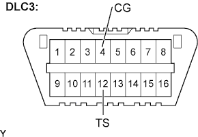
| 1.INSPECT DLC3 TERMINAL VOLTAGE |
Turn the ignition switch to ON.
Measure the voltage.
- Standard voltage:
Tester Connection
| Condition
| Specified Condition
|
TS (12) - CG (4)
| Always
| 11 to 14 V
|
| 2.CHECK HARNESS AND CONNECTOR (DLC3 - BODY GROUND) |
Measure the resistance.
- Standard resistance:
Tester Connection
| Condition
| Specified Condition
|
CG (4) - Body ground
| Always
| Below 1 Ω
|
| | REPAIR OR REPLACE HARNESS OR CONNECTOR |
|
|
| 3.CHECK HARNESS AND CONNECTOR (POWER STEERING ECU - DLC3) |
Disconnect the connector from the power steering ECU.
Measure the resistance.
- Standard resistance:
Tester Connection
| Condition
| Specified Condition
|
TS (D31-11) -TS (12)
| Always
| Below 1 Ω
|
TS (D31-11) - Body ground
| Always
| 10 kΩ or higher
|
| | REPAIR OR REPLACE HARNESS OR CONNECTOR |
|
|