Dtc C1511/11 Torque Sensor 1 Malfunction
DESCRIPTION
WIRING DIAGRAM
INSPECTION PROCEDURE
READ VALUE USING TECHSTREAM
INSPECT POWER STEERING ECU (OUTPUT)
INSPECT STEERING COLUMN ASSEMBLY (TORQUE SENSOR)
DTC C1511/11 Torque Sensor 1 Malfunction |
DTC C1512/12 Torque Sensor Circuit Malfunction |
DTC C1513/13 Torque Sensor Circuit Malfunction |
DTC C1514/14 Torque Sensor Power Source Circuit Malfunction |
DTC C1517/17 Torque Sensor Hold Malfunction |
DESCRIPTION
The torque sensor converts the rotation torque input from the steering wheel into electric signals and sends them to the power steering ECU.DTC No.
| Detection Item
| Trouble Area
|
C1511/11
| Torque sensor (TRQ1) signal error or stop
| - Torque sensor (built into steering column assembly)
- Power steering ECU
|
C1512/12
| Torque sensor (TRQ2) signal error or stop
|
C1513/13
| Deviation between torque sensor TRQ1 and TRQ2 exceeds specified value
|
C1514/14
| Torque sensor power source voltage error
|
C1517/17
| Temporary control due to malfunction related to torque sensor continues for long time
|
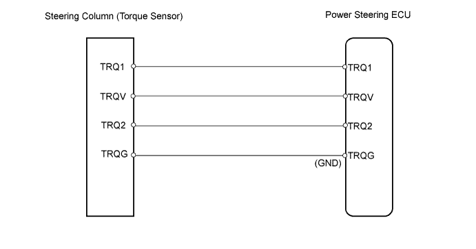
WIRING DIAGRAM
INSPECTION PROCEDURE
| 1.READ VALUE USING TECHSTREAM |
Connect a Techstream to the DLC3.
Turn the ignition switch to ON.
Turn the Techstream on.
Enter the following menus: Chassis / EMPS / Data List.
Select the items "Torque Sensor 1 Output" and "Torque Sensor 2 Output" in the Data List and read the value displayed on the Techstream.
EMPS:Tester Display
| Measurement Item/Range
| Normal Condition
| Diagnostic Note
|
Torque Sensor 1 Output
| Torque sensor 1 voltage:
Minimum: 0.0000 V, Maximum: 5.0000 V
| 2.3 to 2.7 V: Steering wheel not turned (without load)
| Read value with vehicle stopped
|
2.5 to 4.7 V: Steering wheel turned to right
| Read value with vehicle stopped
|
0.3 to 2.5 V: Steering wheel turned to left
| Read value with vehicle stopped
|
Torque Sensor 2 Output
| Torque sensor 2 voltage:
Minimum: 0.0000 V, Maximum: 5.0000 V
| 2.3 to 2.7 V: Steering wheel not turned (without load)
| Read value with vehicle stopped
|
2.5 to 4.7 V: Steering wheel turned to right
| Read value with vehicle stopped
|
0.3 to 2.5 V: Steering wheel turned to left
| Read value with vehicle stopped
|
Check the difference in the values between "Torque Sensor 1 Output" and "Torque Sensor 2 Output".
- OK:
- The voltage difference is below 0.3 V.
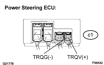
| 2.INSPECT POWER STEERING ECU (OUTPUT) |
Turn the ignition switch to ON.
Measure the voltage.
- Standard voltage:
Tester Connection
| Condition
| Specified condition
|
TRQV (c1-6) - TRQG (c1-8)
| Ignition switch on
| 7.5 to 8.5 V
|
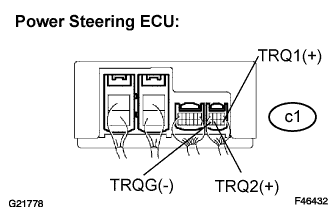
| 3.INSPECT STEERING COLUMN ASSEMBLY (TORQUE SENSOR) |
Turn the ignition switch to ON.
Measure the voltage.
- Standard voltage:
Tester Connection
| Condition (Steering Position)
| Specified Condition
|
TRQ1 (c1-5) - TRQG (c1-8)
| Center position
| 2.3 to 2.7 V
|
TRQ2 (c1-7) - TRQG (c1-8)
| Center position
| 2.3 to 2.7 V
|
TRQ1 (c1-5) - TRQG (c1-8)
| Turned to right
| 2.5 to 4.7 V
|
TRQ2 (c1-7) - TRQG (c1-8)
| Turned to right
| 2.5 to 4.7 V
|
TRQ1 (c1-5) - TRQG (c1-8)
| Turned to left
| 0.3 to 2.5 V
|
TRQ2 (c1-7) - TRQG (c1-8)
| Turned to left
| 0.3 to 2.5 V
|