Automatic Transaxle Unit (For Hatchback) Disassembly
REMOVE TRANSMISSION CONTROL SHAFT LEVER
REMOVE PARK/NEUTRAL POSITION SWITCH ASSEMBLY
REMOVE TRANSMISSION REVOLUTION SENSOR
REMOVE OIL COOLER TUBE UNION
REMOVE NO. 1 TRANSAXLE CASE PLUG
REMOVE TRANSMISSION BREATHER HOSE SUB-ASSEMBLY
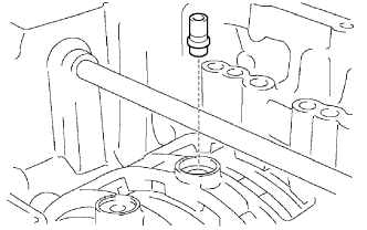
REMOVE BREATHER PLUG
FIX AUTOMATIC TRANSAXLE ASSEMBLY
REMOVE AUTOMATIC TRANSAXLE OIL PAN SUB-ASSEMBLY
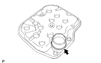
REMOVE VALVE BODY OIL STRAINER ASSEMBLY
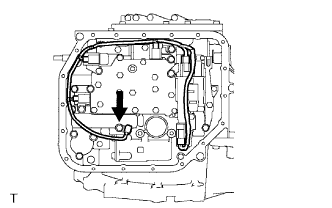
REMOVE TRANSMISSION VALVE BODY ASSEMBLY
REMOVE TRANSMISSION WIRE
REMOVE TRANSAXLE CASE 2ND BRAKE GASKET
REMOVE TRANSAXLE CASE GASKET
REMOVE BRAKE DRUM GASKET
REMOVE CHECK BALL BODY
REMOVE B-2 ACCUMULATOR PISTON
REMOVE C-3 ACCUMULATOR PISTON
REMOVE C-2 ACCUMULATOR PISTON
REMOVE TRANSAXLE HOUSING
INSPECT INPUT SHAFT END PLAY
REMOVE OIL PUMP ASSEMBLY
REMOVE DIFFERENTIAL GEAR ASSEMBLY
REMOVE OVERDRIVE BRAKE GASKET
REMOVE INPUT SHAFT ASSEMBLY
REMOVE STATOR SHAFT THRUST NEEDLE ROLLER BEARING
REMOVE FRONT CLUTCH CLUTCH DISC
REMOVE FORWARD CLUTCH RETURN SPRING SUB-ASSEMBLY
REMOVE FORWARD CLUTCH PISTON
REMOVE FORWARD CLUTCH PISTON O-RING
REMOVE INPUT SHAFT OIL SEAL RING
REMOVE FORWARD CLUTCH HUB THRUST NEEDLE ROLLER BEARING
INSPECT INTERMEDIATE SHAFT ASSEMBLY
REMOVE FORWARD CLUTCH HUB SUB-ASSEMBLY
REMOVE REAR TRANSAXLE COVER ASSEMBLY
REMOVE REAR TRANSAXLE COVER PLUG
REMOVE OVERDRIVE BRAKE RETURN SPRING SUB-ASSEMBLY
REMOVE 2ND COAST AND OVERDRIVE BRAKE PISTON
REMOVE 2ND COAST AND OVERDRIVE O-RING
REMOVE CLUTCH DRUM OIL SEAL RING
REMOVE REAR TRANSAXLE COVER NEEDLE ROLLER BEARING
REMOVE TRANSAXLE CASE GASKET
REMOVE REAR CLUTCH DRUM THRUST NEEDLE ROLLER BEARING
REMOVE INTERMEDIATE SHAFT ASSEMBLY
REMOVE REVERSE CLUTCH DISC
REMOVE DIRECT CLUTCH DISC
REMOVE DIRECT CLUTCH RETURN SPRING SUB-ASSEMBLY
REMOVE DIRECT CLUTCH PISTON SUB-ASSEMBLY
REMOVE DIRECT CLUTCH DRUM SUB-ASSEMBLY
REMOVE DIRECT CLUTCH PISTON O-RING
REMOVE DIRECT CLUTCH DRUM O-RING
REMOVE 2ND COAST AND OVERDRIVE BRAKE DISC
REMOVE THRUST NEEDLE ROLLER BEARING
REMOVE DIRECT CLUTCH HUB
REMOVE REAR NO. 2 PLANETARY SUN GEAR THRUST NEEDLE ROLLER BEARING
REMOVE REAR PLANETARY SUN GEAR ASSEMBLY
REMOVE REAR PLANETARY SUN GEAR THRUST NEEDLE ROLLER BEARING
INSPECT 1-WAY CLUTCH ASSEMBLY
REMOVE 1-WAY CLUTCH ASSEMBLY
REMOVE 2ND COAST AND OVERDRIVE BRAKE FLANGE HOLE SNAP RING
REMOVE 2ND BRAKE BRAKE DISC
REMOVE 2ND BRAKE PISTON SLEEVE
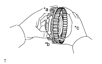
INSPECT NO. 2 1-WAY CLUTCH
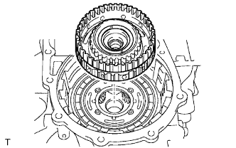
REMOVE REAR PLANETARY GEAR ASSEMBLY
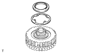
REMOVE REAR PLANETARY GEAR THRUST NEEDLE ROLLER BEARING
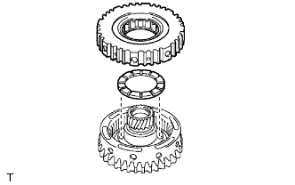
REMOVE NO. 2 1-WAY CLUTCH
REMOVE OUTER RACE RETAINER
REMOVE 2ND BRAKE PISTON RETURN SPRING SUB-ASSEMBLY
REMOVE 2ND BRAKE PISTON
REMOVE 2ND BRAKE CYLINDER O-RING
REMOVE FRONT PLANETARY SUN GEAR
REMOVE 1ST AND REVERSE BRAKE DISC
REMOVE COUNTER DRIVE GEAR NUT
REMOVE PLANETARY GEAR ASSEMBLY
REMOVE COUNTER DRIVE GEAR
REMOVE 1ST AND REVERSE BRAKE RETURN SPRING SUB-ASSEMBLY
REMOVE NO. 2 1ST AND REVERSE BRAKE PISTON
REMOVE NO. 2 1ST AND REVERSE BRAKE PISTON O-RING
REMOVE PARKING LOCK PAWL BRACKET
REMOVE MANUAL VALVE LEVER SHAFT RETAINER SPRING
REMOVE MANUAL VALVE LEVER SUB-ASSEMBLY
REMOVE PARKING LOCK ROD SUB-ASSEMBLY
REMOVE MANUAL VALVE LEVER SHAFT
REMOVE PARKING LOCK PAWL
REMOVE DIFFERENTIAL DRIVE PINION SUB-ASSEMBLY
REMOVE DIFFERENTIAL DRIVE PINION PLUG
REMOVE BEARING LOCK PLATE
REMOVE DIFFERENTIAL GEAR LUBE APPLY TUBE
REMOVE FRONT DRIVE PINION FRONT TAPERED ROLLER BEARING
REMOVE FRONT DRIVE PINION REAR TAPERED ROLLER BEARING
REMOVE COUNTER DRIVE GEAR BEARING
REMOVE COUNTER DRIVE GEAR HOLE SNAP RING
REMOVE MANUAL VALVE LEVER SHAFT OIL SEAL
REMOVE FRONT TRANSAXLE CASE OIL SEAL
REMOVE TRANSAXLE CASE OIL SEAL
Automatic Transaxle Unit (For Hatchback) -- Disassembly |
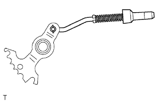
| 1. REMOVE TRANSMISSION CONTROL SHAFT LEVER |
Remove the nut, washer and the transmission control shaft lever.
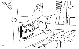
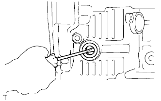
| 2. REMOVE PARK/NEUTRAL POSITION SWITCH ASSEMBLY |
Using a screwdriver, pry out the lock plate and remove the nut, lock plate and washer.
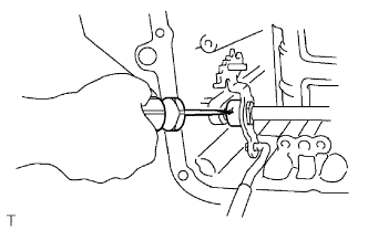
Remove the 2 bolts and pull out the park/neutral position switch assembly.
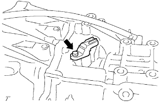
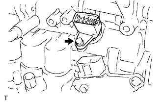
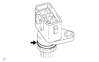
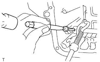
| 3. REMOVE TRANSMISSION REVOLUTION SENSOR |
Remove the bolt and the transmission revolution sensor.
Remove the O-ring from the transmission revolution sensor.
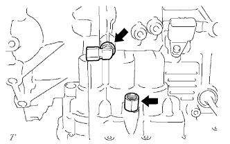
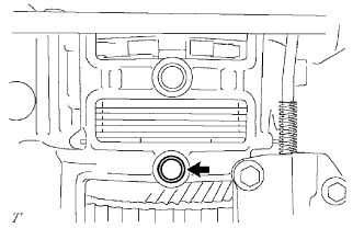
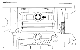
| 4. REMOVE OIL COOLER TUBE UNION |
Remove the 2 oil cooler tube unions from the transaxle case.
Remove the 2 O-rings from the 2 oil cooler tube unions.
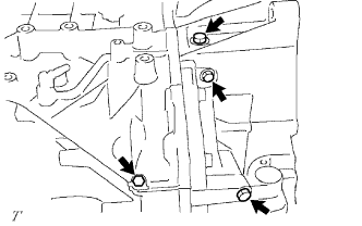
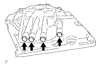
| 5. REMOVE NO. 1 TRANSAXLE CASE PLUG |
Remove the 4 No. 1 transaxle case plugs from the transaxle housing and the transaxle case.
Remove the No. 1 transaxle case plug from the transaxle case.
Remove the 5 O-rings from each No. 1 transaxle case plugs.
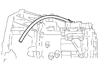
| 6. REMOVE TRANSMISSION BREATHER HOSE SUB-ASSEMBLY |
Remove the transmission breather hose sub-assembly from the breather plug.
Remove the breather plug from the transaxle case.
Remove the O-ring from the breather plug.
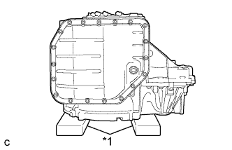
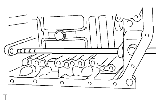
| 8. FIX AUTOMATIC TRANSAXLE ASSEMBLY |
Secure the transaxle on wooden blocks.
Text in Illustration*1
| Wooden Block
|
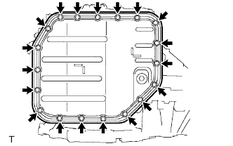
| 9. REMOVE AUTOMATIC TRANSAXLE OIL PAN SUB-ASSEMBLY |
Remove the drain plug and gasket from the automatic transaxle oil pan sub-assembly.
Remove the 19 bolts, automatic transaxle oil pan sub-assembly and the automatic transaxle oil pan gasket.
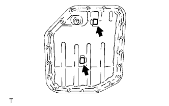
Remove the 2 oil cleaner magnets from the automatic transaxle oil pan sub-assembly.
Examine the particles in the automatic transaxle oil pan gasket.
Collect any steel chips with the removed magnets.
Carefully look at the foreign matter and particles in the automatic transaxle oil pan gasket and on the magnets to predict the type of wear which might be found in the transaxle.
Steel (magnetic): bearing, gear and clutch plate wear
Brass (non-magnetic): bearing wear
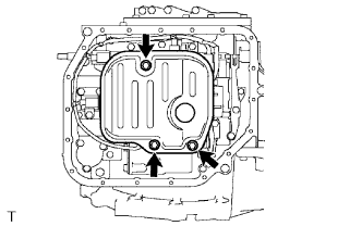
| 10. REMOVE VALVE BODY OIL STRAINER ASSEMBLY |
Remove the 3 bolts and the valve body oil strainer assembly.
Remove the oil strainer gasket from the valve body oil strainer assembly.
| 11. REMOVE TRANSMISSION VALVE BODY ASSEMBLY |
Disconnect the 5 connectors from the transmission valve body assembly.
Remove the bolt and the lock plate, and separate the transmission wire.
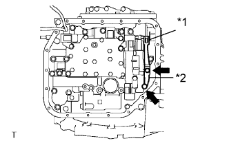
Remove the 2 bolts, manual detent spring cover and the manual detent spring.
Text in Illustration*1
| Manual Detent Spring
|
*2
| Manual Detent Spring Cover
|
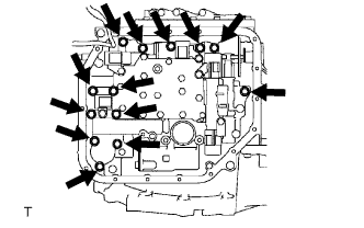
Remove the 13 bolts and the transmission valve body assembly from the transaxle case.
| 12. REMOVE TRANSMISSION WIRE |
Remove the bolt and the transmission wire from the transaxle case.
Remove the O-ring from the transmission wire.
| 13. REMOVE TRANSAXLE CASE 2ND BRAKE GASKET |
Remove the transaxle case 2nd brake gasket from the transaxle case.
| 14. REMOVE TRANSAXLE CASE GASKET |
Remove the transaxle case gasket from the transaxle case.
| 15. REMOVE BRAKE DRUM GASKET |
Remove the brake drum gasket from the transaxle case.
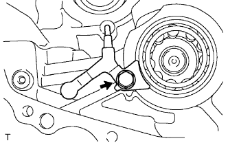
| 16. REMOVE CHECK BALL BODY |
Remove the check ball body and the check ball body compression spring from the transaxle case.
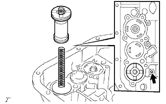
| 17. REMOVE B-2 ACCUMULATOR PISTON |
Apply compressed air (392 kPa, 4.0 kgf/cm2, 57 psi) to the oil hole and remove the B-2 accumulator piston and the B-2 accumulator piston compression spring.
- NOTICE:
- Blowing the air may cause the piston to jump out. When removing the piston, hold it by hand using a piece of cloth.
- Do not splash ATF with the compressed air.
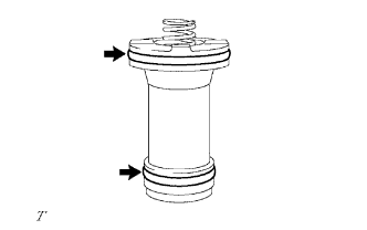
Remove the 2 B-2 accumulator piston O-rings from the B-2 accumulator piston.
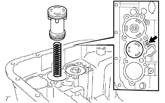
| 18. REMOVE C-3 ACCUMULATOR PISTON |
Apply compressed air (392 kPa, 4.0 kgf/cm2, 57 psi) to the oil hole and remove the C-3 accumulator piston and the C-3 accumulator piston compression spring.
- NOTICE:
- Blowing the air may cause the piston to jump out. When removing the piston, hold it with your hand using a piece of cloth.
- Do not splash ATF with the compressed air.
Remove the 2 C-3 accumulator piston O-rings from the C-3 accumulator piston.
| 19. REMOVE C-2 ACCUMULATOR PISTON |
Apply compressed air (392 kPa, 4.0 kgf/cm2, 57 psi) to the oil hole and remove the C-2 accumulator piston and the C-2 accumulator piston compression spring.
- NOTICE:
- Blowing the air may cause the piston to jump out. When removing the piston, hold it by hand using a piece of cloth.
- Do not splash ATF with the compressed air.
Remove the 2 C-2 accumulator piston O-rings from the C-2 accumulator piston.
| 20. REMOVE TRANSAXLE HOUSING |
Remove the 14 bolts.
Tap around the circumference of the transaxle housing with a plastic hammer to remove the transaxle housing from the transaxle case.
- NOTICE:
- The differential gear assembly may be accidentally removed when the transaxle housing is removed.
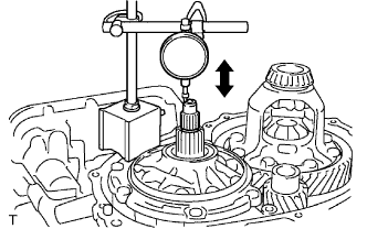
| 21. INSPECT INPUT SHAFT END PLAY |
Measure the end play in the axial direction.
- End play:
- 0.37 to 1.29 mm (0.0146 to 0.0508 in.)
If the end play is not as specified, select and replace the thrust needle roller bearing.
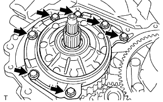
| 22. REMOVE OIL PUMP ASSEMBLY |
Remove the 7 bolts and the oil pump assembly from the transaxle case.
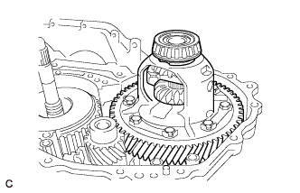
| 23. REMOVE DIFFERENTIAL GEAR ASSEMBLY |
Remove the differential gear assembly from the transaxle case.
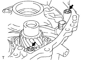
| 24. REMOVE OVERDRIVE BRAKE GASKET |
Using a screwdriver, remove the 2 overdrive brake gaskets from the transaxle case.
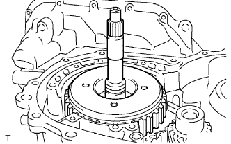
| 25. REMOVE INPUT SHAFT ASSEMBLY |
Remove the input shaft assembly from the transaxle case.
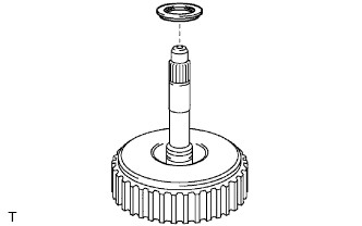
| 26. REMOVE STATOR SHAFT THRUST NEEDLE ROLLER BEARING |
Remove the stator shaft thrust needle roller bearing from the input shaft assembly.
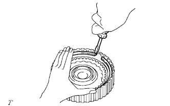
| 27. REMOVE FRONT CLUTCH CLUTCH DISC |
Using a screwdriver, remove the snap ring.
Remove the forward clutch flange, 4 front clutch clutch discs and the 4 No. 1 clutch plates from the input shaft sub-assembly.
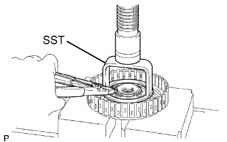
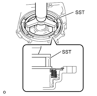
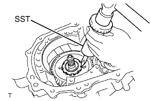
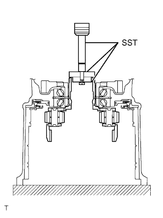
| 28. REMOVE FORWARD CLUTCH RETURN SPRING SUB-ASSEMBLY |
Using SST on the No. 1 clutch balancer, compress the forward clutch return spring sub-assembly with a press.
- SST
- 09320-89010
- NOTICE:
- Do not compress the return spring excessively.
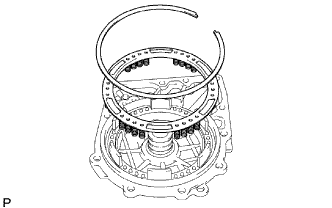
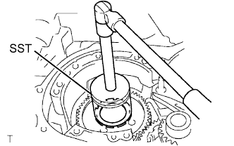
Using a snap ring expander, remove the snap ring.
Remove the No. 1 clutch balancer and the forward clutch return spring sub-assembly.
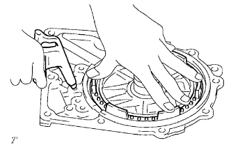
| 29. REMOVE FORWARD CLUTCH PISTON |
Place the input shaft onto the oil pump.
Holding the forward clutch piston by hand, apply compressed air (392 kPa, 4.0 kgf/cm2, 57 psi) to the oil pump to remove the forward clutch piston.
- HINT:
- When the piston cannot be removed due to being slanted, either blow the air again with the protruding side pushed or remove the piston using needle-nose pliers with their tips wrapped in protective tape.
| 30. REMOVE FORWARD CLUTCH PISTON O-RING |
Using a screwdriver, remove the forward clutch piston O-ring from the forward clutch piston.
| 31. REMOVE INPUT SHAFT OIL SEAL RING |
Using a screwdriver, remove the input shaft oil seal ring from the input shaft sub-assembly.
| 32. REMOVE FORWARD CLUTCH HUB THRUST NEEDLE ROLLER BEARING |
Remove the forward clutch hub thrust needle roller bearing from the forward clutch hub sub-assembly.
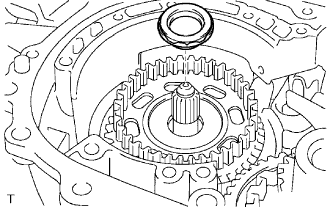
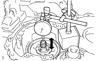
| 33. INSPECT INTERMEDIATE SHAFT ASSEMBLY |
Using a dial indicator, measure the clearance of the intermediate shaft assembly.
- Standard clearance:
- 0.204 to 0.966 mm (0.00803 to 0.03803 in.)
If the clearance is outside the specification, replace the rear clutch drum thrust needle roller bearing.
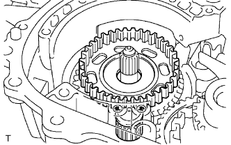
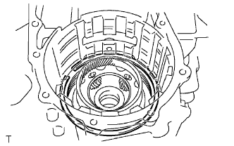
| 34. REMOVE FORWARD CLUTCH HUB SUB-ASSEMBLY |
Remove the forward clutch hub sub-assembly from the transaxle case.
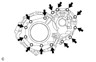
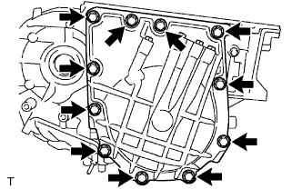
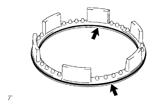
| 35. REMOVE REAR TRANSAXLE COVER ASSEMBLY |
Remove the 11 bolts.
Tap around the circumference of the rear transaxle cover with a plastic hammer to remove the rear transaxle cover assembly from the transaxle case.
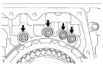
| 36. REMOVE REAR TRANSAXLE COVER PLUG |
Remove the 4 rear transaxle cover plugs from the rear transaxle cover.
Using a screwdriver, remove the 4 O-rings from the 4 rear transaxle cover plugs.
| 37. REMOVE OVERDRIVE BRAKE RETURN SPRING SUB-ASSEMBLY |
Using SST, a press and a screwdriver, remove the snap ring.
- SST
- 09387-00070
- NOTICE:
- Stop the press when the overdrive brake piston is lowered to 1 to 2 mm (0.0394 to 0.0787 in.) from the snap ring groove, to prevent the overdrive brake piston from being deformed.
Remove the overdrive brake return spring sub-assembly from the rear transaxle cover.
| 38. REMOVE 2ND COAST AND OVERDRIVE BRAKE PISTON |
Apply compressed air (392 kPa, 4.0 kgf/cm2, 57 psi) to the rear transaxle cover to remove the 2nd coast and overdrive brake piston.
- NOTICE:
- Blowing the air may cause the piston to jump out. When removing the piston, hold it by hand using a piece of cloth.
- Do not splash ATF with the compressed air.
| 39. REMOVE 2ND COAST AND OVERDRIVE O-RING |
Using a screwdriver, remove the 2 2nd coast and overdrive O-rings from the 2nd coast and overdrive brake piston.
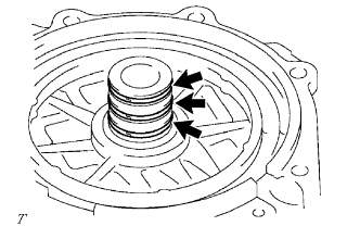
| 40. REMOVE CLUTCH DRUM OIL SEAL RING |
Remove the 3 clutch drum oil seal rings from the rear transaxle cover.
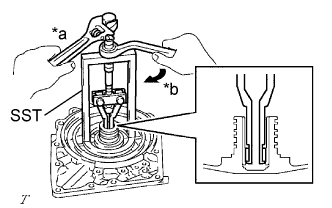
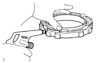
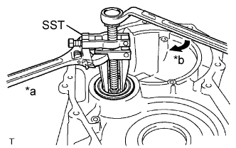
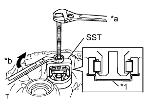
| 41. REMOVE REAR TRANSAXLE COVER NEEDLE ROLLER BEARING |
Using SST, remove the rear transaxle cover needle roller bearing from the rear transaxle cover.
Text in Illustration*a
| Hold
|
*b
| Turn
|
- SST
- 09387-00041(09387-01021)
| 42. REMOVE TRANSAXLE CASE GASKET |
Remove the 4 transaxle case gaskets from the transaxle case.
| 43. REMOVE REAR CLUTCH DRUM THRUST NEEDLE ROLLER BEARING |
Using a magnet hand, remove the rear clutch drum thrust needle roller bearing.
| 44. REMOVE INTERMEDIATE SHAFT ASSEMBLY |
Remove the intermediate shaft assembly from the transaxle case.
| 45. REMOVE REVERSE CLUTCH DISC |
Using a screwdriver, remove the snap ring from the intermediate shaft.
Remove the reverse clutch flange, 2 reverse clutch discs and the 2 No. 3 clutch plates from the intermediate shaft.
| 46. REMOVE DIRECT CLUTCH DISC |
Using a screwdriver, remove the snap ring from the intermediate shaft.
Remove the direct clutch flange, 3 direct clutch disc and the 3 rear clutch flanges from the intermediate shaft.
| 47. REMOVE DIRECT CLUTCH RETURN SPRING SUB-ASSEMBLY |
Using SST, a press and snap ring expander, remove the snap ring from the direct clutch piston sub-assembly.
- SST
- 09387-00020
Remove the direct clutch return spring sub-assembly from the intermediate shaft.
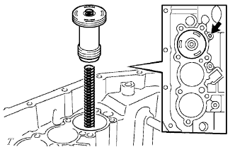
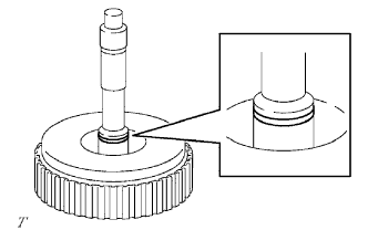
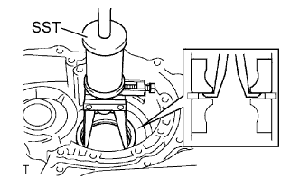
| 48. REMOVE DIRECT CLUTCH PISTON SUB-ASSEMBLY |
Install the intermediate shaft onto the rear transaxle cover.
Apply compressed air (392 kPa, 4.0 kgf/cm2, 57 psi) to the oil hole shown in the illustration and remove the direct clutch piston sub-assembly from the intermediate shaft.
- NOTICE:
- Blowing the air may cause the piston to jump out. When removing the piston, hold it by hand using a piece of cloth.
- Do not splash ATF with the compressed air.
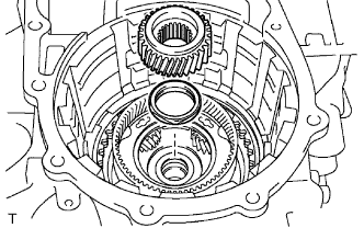
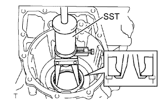
| 49. REMOVE DIRECT CLUTCH DRUM SUB-ASSEMBLY |
Install the intermediate shaft onto the rear transaxle cover.
Put a matchmark on the direct clutch drum sub-assembly in the same position as the cutout of the intermediate shaft.
Apply compressed air (392 kPa, 4.0 kgf/cm2, 57 psi) to the oil hole shown in the illustration and remove the direct clutch drum sub-assembly from the intermediate shaft.
- NOTICE:
- Blowing the air may cause the drum to jump out. When removing the drum, hold it by hand using a piece of cloth.
- Do not splash ATF with the compressed air.
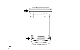
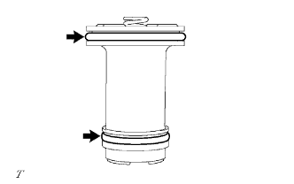
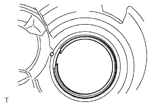
| 50. REMOVE DIRECT CLUTCH PISTON O-RING |
Using a screwdriver, remove the 2 direct clutch piston O-rings from the direct clutch piston sub-assembly.
| 51. REMOVE DIRECT CLUTCH DRUM O-RING |
Using a screwdriver, remove the direct clutch drum O-ring from the direct clutch drum sub-assembly.
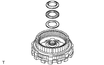
| 52. REMOVE 2ND COAST AND OVERDRIVE BRAKE DISC |
Remove the 2nd coast and overdrive brake flange, 2 2nd coast and overdrive brake discs and the 2 No. 2 2nd coast and overdrive brake flanges from the transaxle case.
| 53. REMOVE THRUST NEEDLE ROLLER BEARING |
Using a magnet hand, remove the C-2 hub thrust bearing race, thrust needle roller bearing and the No. 3 thrust bearing race from the direct clutch hub.
| 54. REMOVE DIRECT CLUTCH HUB |
Remove the direct clutch hub from the transaxle case.
| 55. REMOVE REAR NO. 2 PLANETARY SUN GEAR THRUST NEEDLE ROLLER BEARING |
Using a magnet hand, remove the rear No. 2 planetary sun gear thrust needle roller bearing from the rear planetary sun gear assembly.
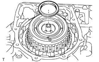
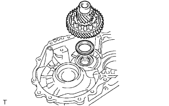
| 56. REMOVE REAR PLANETARY SUN GEAR ASSEMBLY |
Remove the rear planetary sun gear assembly from the transaxle case.
| 57. REMOVE REAR PLANETARY SUN GEAR THRUST NEEDLE ROLLER BEARING |
Remove the rear planetary sun gear thrust needle roller bearing and the No. 1 planetary carrier thrust washer from the rear planetary sun gear assembly.
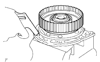
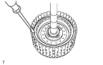
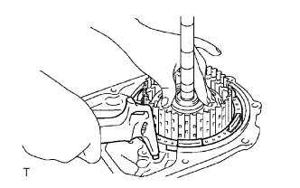
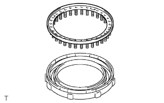
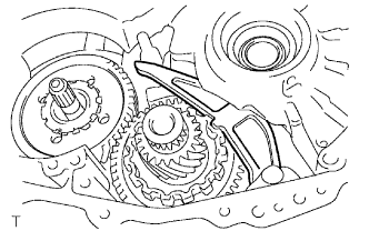
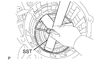
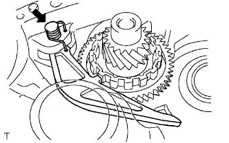
| 58. INSPECT 1-WAY CLUTCH ASSEMBLY |
Hold the rear planetary sun gear and turn the 1-way clutch assembly.
Text in Illustration*a
| Free
|
*b
| Lock
|
*c
| Hold
|
Make sure that 1-way clutch assembly turns freely counterclockwise and locks when turned clockwise.
If the 1-way clutch assembly does not operate normally, replace it.
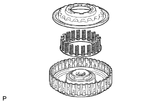
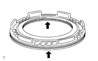
| 59. REMOVE 1-WAY CLUTCH ASSEMBLY |
Remove the 1-way clutch assembly and the No. 2 planetary carrier thrust washer from the rear planetary sun gear assembly.
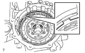
| 60. REMOVE 2ND COAST AND OVERDRIVE BRAKE FLANGE HOLE SNAP RING |
Using a screwdriver, remove the 2nd coast and overdrive brake flange hole snap ring from the transaxle case.
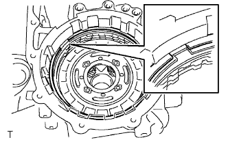
| 61. REMOVE 2ND BRAKE BRAKE DISC |
Using a screwdriver, remove the snap ring from the transaxle case.
Remove the 2nd brake brake flange, 3 2nd brake brake discs and the 3 No. 1 2nd brake brake flanges from the transaxle case.
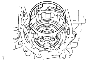
| 62. REMOVE 2ND BRAKE PISTON SLEEVE |
Remove the 2nd brake piston sleeve from the transaxle case.
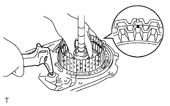
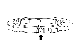
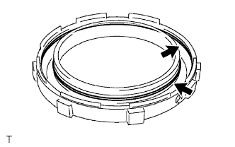
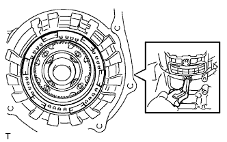
| 63. INSPECT NO. 2 1-WAY CLUTCH |
Hold the rear planetary gear assembly and turn the No. 2 1-way clutch.
Text in Illustration
| Lock
|

| Free
|
Make sure that the No. 2 1-way clutch turns freely counterclockwise and locks when turned clockwise.
If the No. 2 1-way clutch does not operate normally, replace it.
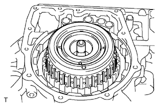
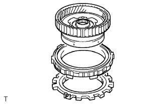
| 64. REMOVE REAR PLANETARY GEAR ASSEMBLY |
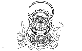
Using a screwdriver, remove the snap ring from the transaxle case.
Remove the rear planetary gear assembly from the transaxle case.
| 65. REMOVE REAR PLANETARY GEAR THRUST NEEDLE ROLLER BEARING |
Remove the rear planetary gear thrust needle roller bearing, No. 2 thrust bearing race and the thrust bearing race from the rear planetary gear assembly.
| 66. REMOVE NO. 2 1-WAY CLUTCH |
Remove the No. 2 1-way clutch, 2nd brake piston assembly from the rear planetary gear assembly.
| 67. REMOVE OUTER RACE RETAINER |
Remove the outer race retainer from the No. 2 1-way clutch.
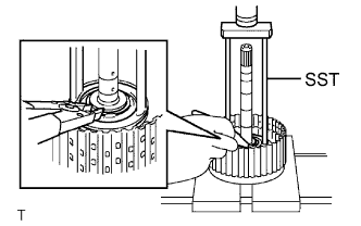
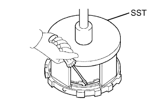
| 68. REMOVE 2ND BRAKE PISTON RETURN SPRING SUB-ASSEMBLY |
Using SST and a press, remove the snap ring.
- SST
- 09387-00060
Remove the 2nd brake piston return spring sub-assembly from the 2nd brake cylinder.
| 69. REMOVE 2ND BRAKE PISTON |
Hold the 2nd brake piston and apply compressed air (392 kPa, 4.0 kgf/cm2, 57 psi) to the 2nd brake cylinder to remove the 2nd brake piston.
| 70. REMOVE 2ND BRAKE CYLINDER O-RING |
Using a screwdriver, remove the 2 2nd brake cylinder O-rings from the 2nd brake cylinder.
| 71. REMOVE FRONT PLANETARY SUN GEAR |
Remove the front planetary sun gear and the front planetary gear thrust needle roller bearing from the transaxle case.
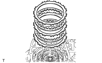
| 72. REMOVE 1ST AND REVERSE BRAKE DISC |
Using a screwdriver, remove the snap ring from the transaxle case.
Remove the 1st and reverse brake flange, 4 1st and reverse brake discs and the 4 1st and reverse brake plates from the transaxle case.
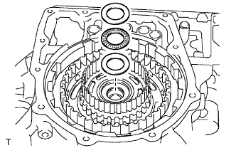
| 73. REMOVE COUNTER DRIVE GEAR NUT |
Fix the counter drive gear with the parking lock pawl.
Using SST and a hammer, release the counter drive gear lock nut washer.
- SST
- 09930-00010
Using SST, remove the counter drive gear nut and the counter drive gear lock nut washer.
- SST
- 09387-00121
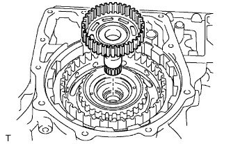
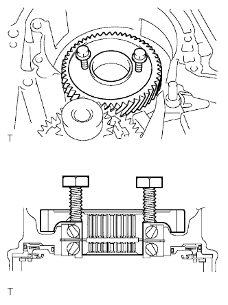
| 74. REMOVE PLANETARY GEAR ASSEMBLY |
Using SST and a press, remove the planetary gear assembly from the transaxle case.
- SST
- 09950-60010(09951-00400,09951-00320,09952-06010)
09950-70010(09951-07100)
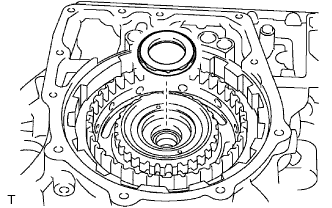
| 75. REMOVE COUNTER DRIVE GEAR |
Install the 2 bolts to the counter drive gear.
- Recommended service bolt:
- Diameter:
- 10 mm
- Pitch:
- 1.25 mm
- Length:
- 40 to 80 mm (1.575 to 3.150 in.)
Rotate the 2 bolts and remove the counter drive gear.
| 76. REMOVE 1ST AND REVERSE BRAKE RETURN SPRING SUB-ASSEMBLY |
Using SST, a press and screwdriver, remove the snap ring from the transaxle case.
- SST
- 09387-00070
Remove the 1st and reverse brake return spring sub-assembly from the transaxle case.
| 77. REMOVE NO. 2 1ST AND REVERSE BRAKE PISTON |
Apply compressed air (392 kPa, 4.0 kgf/cm2, 57 psi) to the transaxle case to remove the 1st and reverse brake piston.
- NOTICE:
- Blowing the air may cause the piston to jump out. When removing the piston, hold it by hand using a piece of cloth.
- Do not splash ATF with the compressed air.
| 78. REMOVE NO. 2 1ST AND REVERSE BRAKE PISTON O-RING |
Remove the 2 No. 2 1st and reverse brake piston O-rings from the No. 2 1st and reverse brake piston.
| 79. REMOVE PARKING LOCK PAWL BRACKET |
Remove the 3 bolts, parking lock cam guide and the parking lock pawl bracket from the transaxle case.
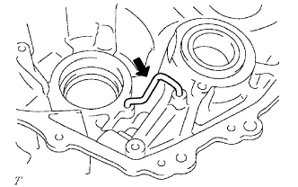
| 80. REMOVE MANUAL VALVE LEVER SHAFT RETAINER SPRING |
Remove the manual valve lever shaft retainer spring from the manual valve lever shaft.
| 81. REMOVE MANUAL VALVE LEVER SUB-ASSEMBLY |
Using a screwdriver, release and remove the manual valve lever shaft spacer.
Using a pin punch 3 mm and hammer, drive out the manual valve lever shaft spring pin.
Remove the manual valve lever shaft and manual valve lever sub-assembly.
| 82. REMOVE PARKING LOCK ROD SUB-ASSEMBLY |
Remove the parking lock rod sub-assembly from the manual valve lever sub-assembly.
| 83. REMOVE MANUAL VALVE LEVER SHAFT |
Remove the manual valve lever shaft from the transaxle case.
| 84. REMOVE PARKING LOCK PAWL |
Using a screwdriver, remove the parking lock pawl shaft from the transaxle case.
Remove the parking lock pawl torsion spring and the parking lock pawl from the transaxle case.
| 85. REMOVE DIFFERENTIAL DRIVE PINION SUB-ASSEMBLY |
Remove the differential drive pinion sub-assembly and the drive pinion thrust bearing LH from the transaxle case.
| 86. REMOVE DIFFERENTIAL DRIVE PINION PLUG |
Using a brass bar and hammer, remove the differential drive pinion plug.
| 87. REMOVE BEARING LOCK PLATE |
Remove the bolt and the bearing lock plate.
| 88. REMOVE DIFFERENTIAL GEAR LUBE APPLY TUBE |
Remove the differential gear lube apply tube from the transaxle housing.
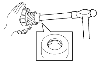
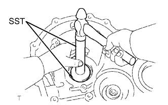
| 89. REMOVE FRONT DRIVE PINION FRONT TAPERED ROLLER BEARING |
Using SST, remove the front drive pinion front tapered roller bearing from the transaxle housing.
Text in Illustration*a
| Hold
|
*b
| Turn
|
- SST
- 09308-10010
Remove the drive pinion thrust bearing RH from the transaxle housing.
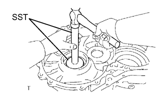
| 90. REMOVE FRONT DRIVE PINION REAR TAPERED ROLLER BEARING |
Using SST, remove the front drive pinion rear tapered roller bearing from the transaxle case.
Text in Illustration*1
| No. 1 Transaxle Case Plate
|
*a
| Hold
|
*b
| Turn
|
- SST
- 09612-65014(09612-01040)
Remove the No. 1 transaxle case plate from the transaxle case.
| 91. REMOVE COUNTER DRIVE GEAR BEARING |
Remove the 2 counter drive gear bearing inner races and 2 angular balls from the transaxle case.
Using SST, remove the counter drive gear bearing outer race from the transaxle case.
- SST
- 09308-00010
Using SST, remove the counter drive gear bearing outer race from the transaxle case.
- SST
- 09308-00010
| 92. REMOVE COUNTER DRIVE GEAR HOLE SNAP RING |
Using a screwdriver, remove the counter drive gear hole snap ring from the transaxle case.
| 93. REMOVE MANUAL VALVE LEVER SHAFT OIL SEAL |
Using a screwdriver, remove the manual valve lever shaft oil seal from the transaxle case.
| 94. REMOVE FRONT TRANSAXLE CASE OIL SEAL |
Using SST and a hammer, remove the front transaxle case oil seal from the transaxle case.
- SST
- 09950-60010(09951-00530)
09950-70010(09951-07100)
| 95. REMOVE TRANSAXLE CASE OIL SEAL |
Using SST and a hammer, remove the transaxle case oil seal from the transaxle housing.
- SST
- 09950-60010(09951-00550)
09950-70010(09951-07100)