Automatic Transaxle Assembly (For Sedan) Removal
REMOVE HOOD SUB-ASSEMBLY
REMOVE FRONT WHEELS
REMOVE ENGINE UNDER COVER LH
REMOVE ENGINE UNDER COVER RH
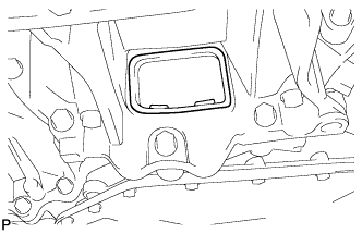
DRAIN AUTOMATIC TRANSAXLE FLUID
REMOVE FRONT WIPER ARM HEAD CAP
REMOVE FRONT WIPER ARM AND BLADE ASSEMBLY LH
REMOVE FRONT WIPER ARM AND BLADE ASSEMBLY RH
REMOVE COWL SIDE VENTILATOR SUB-ASSEMBLY LH
REMOVE COWL SIDE VENTILATOR SUB-ASSEMBLY RH
REMOVE COWL TOP VENTILATOR LOUVER SUB-ASSEMBLY
REMOVE FRONT WIPER MOTOR AND LINK
REMOVE FRONT AIR SHUTTER SEAL
REMOVE OUTER COWL TOP PANEL
REMOVE BATTERY
REMOVE BATTERY TRAY
REMOVE BATTERY CARRIER
REMOVE NO. 2 CYLINDER HEAD COVER
REMOVE AIR CLEANER ASSEMBLY
REMOVE AIR CLEANER BRACKET
POSITION WHEELS FACING STRAIGHT AHEAD
REMOVE COLUMN HOLE COVER SILENCER SHEET
SEPARATE STEERING SLIDING YOKE SUB-ASSEMBLY
SEPARATE NO. 1 STEERING COLUMN HOLE COVER SUB-ASSEMBLY
SEPARATE TRANSMISSION CONTROL CABLE ASSEMBLY
SEPARATE NO. 3 ENGINE WIRE
DISCONNECT CONNECTORS
DISCONNECT WIRE HARNESS
REMOVE STARTER ASSEMBLY
REMOVE FRONT AXLE HUB NUT LH
REMOVE FRONT AXLE HUB NUT RH
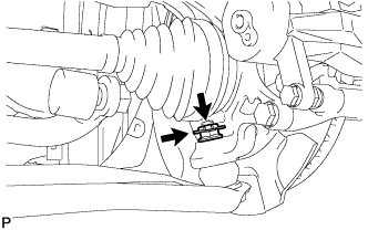
SEPARATE FRONT SPEED SENSOR LH (w/ ABS)
SEPARATE FRONT SPEED SENSOR RH (w/ ABS)
SEPARATE FRONT STABILIZER LINK ASSEMBLY LH
SEPARATE FRONT STABILIZER LINK ASSEMBLY RH
SEPARATE TIE ROD END SUB-ASSEMBLY LH
SEPARATE TIE ROD END SUB-ASSEMBLY RH
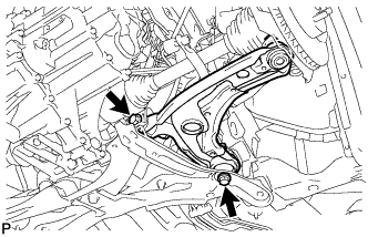
SEPARATE FRONT LOWER SUSPENSION ARM LH
SEPARATE FRONT LOWER SUSPENSION ARM RH
SEPARATE FRONT AXLE ASSEMBLY LH
SEPARATE FRONT AXLE ASSEMBLY RH
REMOVE AUTOMATIC TRANSMISSION CASE PROTECTOR (w/o ABS)
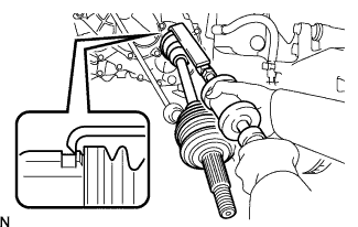
REMOVE FRONT DRIVE SHAFT ASSEMBLY LH
REMOVE FRONT DRIVE SHAFT ASSEMBLY RH
SUSPEND ENGINE ASSEMBLY
SEPARATE INLET OIL COOLER HOSE
SEPARATE OUTLET OIL COOLER HOSE
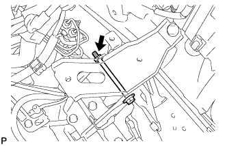
SEPARATE ENGINE MOVING CONTROL ROD
REMOVE FRONT SUSPENSION CROSSMEMBER SUB-ASSEMBLY
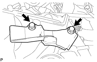
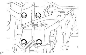
REMOVE ENGINE MOVING CONTROL ROD BRACKET
SUPPORT AUTOMATIC TRANSAXLE ASSEMBLY
SEPARATE ENGINE MOUNTING INSULATOR LH
REMOVE ENGINE MOUNTING BRACKET LH
REMOVE AUTOMATIC TRANSAXLE ASSEMBLY
REMOVE TORQUE CONVERTER CLUTCH ASSEMBLY
REMOVE NO. 1 TRANSMISSION CONTROL CABLE BRACKET
SEPARATE INLET NO. 1 OIL COOLER TUBE
SEPARATE OUTLET NO. 1 OIL COOLER TUBE
REMOVE NO. 2 OIL COOLER TUBE CLAMP
REMOVE TRANSMISSION OIL LEVEL GAUGE SUB-ASSEMBLY
REMOVE TRANSMISSION OIL FILLER TUBE SUB-ASSEMBLY
Automatic Transaxle Assembly (For Sedan) -- Removal |
| 1. REMOVE HOOD SUB-ASSEMBLY |
Remove the 4 bolts and remove the hood.
| 3. REMOVE ENGINE UNDER COVER LH |
| 4. REMOVE ENGINE UNDER COVER RH |
| 5. DRAIN AUTOMATIC TRANSAXLE FLUID |
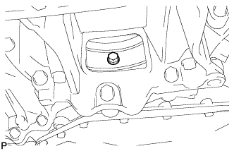
Remove the drain plug and gasket, and drain the ATF.
Install a new gasket and the drain plug.
- Torque:
- 49 N*m{500 kgf*cm, 36 ft.*lbf}
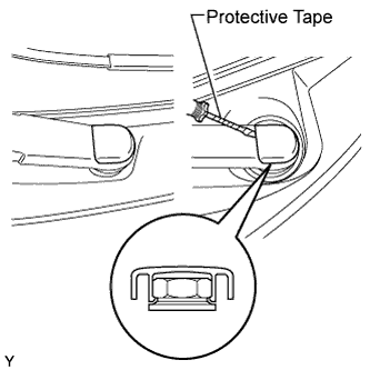
| 6. REMOVE FRONT WIPER ARM HEAD CAP |
Using a screwdriver with its tip wrapped in protective tape, disengage the claw and remove the 2 front wiper arm head caps.
| 7. REMOVE FRONT WIPER ARM AND BLADE ASSEMBLY LH |
Operate the wiper, then stop the windshield wiper motor in the automatic stop position.
Remove the nut and front wiper arm.
| 8. REMOVE FRONT WIPER ARM AND BLADE ASSEMBLY RH |
- HINT:
- Use the same procedure as for the LH side.
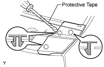
| 9. REMOVE COWL SIDE VENTILATOR SUB-ASSEMBLY LH |
Using a screwdriver with its tip wrapped in protective tape, disengage the 3 claws and remove the cowl side ventilator sub-assembly LH.
| 10. REMOVE COWL SIDE VENTILATOR SUB-ASSEMBLY RH |
- HINT:
- Use the same procedure as for the LH side.
| 11. REMOVE COWL TOP VENTILATOR LOUVER SUB-ASSEMBLY |
Disengage the 3 clips, the 4 claws and the 8 hooks.
Remove the cowl top ventilator louver sub-assembly.
Disconnect the washer hoses.
Disengage the 5 hooks.
| 12. REMOVE FRONT WIPER MOTOR AND LINK |
Remove the 2 bolts.
Slide the wiper link. Disengage the meshing of the rubber pin, then disconnect the connector and remove the front wiper motor and link.
| 13. REMOVE FRONT AIR SHUTTER SEAL |
Disengage the 3 claws and remove the front air shutter seal.
| 14. REMOVE OUTER COWL TOP PANEL |
Disengage the claw and disconnect the wire harness.
Remove the 2 bolts and remove the cowl top panel outer center bracket.
Remove the 8 bolts and remove the cowl top panel outer.
Disconnect the cable from the battery terminal.
Loosen the nut and remove the battery clamp.
Remove the battery.
| 17. REMOVE BATTERY CARRIER |
Separate the wire harness clamp from the battery carrier.
Remove the 5 bolts and remove the battery carrier.
| 18. REMOVE NO. 2 CYLINDER HEAD COVER |
Remove the 4 nuts and No. 2 cylinder head cover.
| 19. REMOVE AIR CLEANER ASSEMBLY |
Separate the intake air flow meter connector and the wire harness clamp.
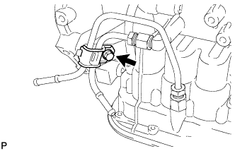
Separate the fuel vapor feed hose from the vacuum switching valve assembly and air cleaner hose.
Separate the vacuum switching valve connector and the wire harness clamp.
Separate the ventilation hose from the air cleaner hose.
Release the air cleaner cap sub-assembly with No. 1 air cleaner hose.
Loosen the air cleaner hose clamp on the throttle body side and remove the air cleaner cap and the air cleaner hose.
Remove the air cleaner element.
Separate the wire harness clamp from the air cleaner case.
Remove the 2 bolts and remove the air cleaner case with No. 1 air cleaner inlet.
| 20. REMOVE AIR CLEANER BRACKET |
Separate the wire harness clamp from the air cleaner bracket.
Remove the 2 bolts and remove the air cleaner bracket.
| 21. POSITION WHEELS FACING STRAIGHT AHEAD |
| 22. REMOVE COLUMN HOLE COVER SILENCER SHEET |
Pull back the floor carpet, remove the 2 clips and remove the column hole cover silencer sheet.
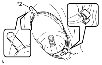
| 23. SEPARATE STEERING SLIDING YOKE SUB-ASSEMBLY |
Use a seat belt to fix the steering wheel assembly, in order to avoid breakage of the spiral cable.
Place matchmarks on the sliding yoke of the steering intermediate shaft assembly and the steering gear assembly.
Text in Illustration*1
| Bolt A
|
*2
| Bolt B
|
*a
| Matchmark
|
Loosen bolt A, remove bolt B and separate the steering intermediate shaft assembly.
| 24. SEPARATE NO. 1 STEERING COLUMN HOLE COVER SUB-ASSEMBLY |
Remove clip A, separate clip B from the body and separate No. 1 steering column hole cover sub-assembly.
Text in Illustration*1
| Clip A
|
*2
| Clip B
|
| 25. SEPARATE TRANSMISSION CONTROL CABLE ASSEMBLY |
Remove the nut and disconnect the control cable from the control shaft lever.
Remove the clip and disconnect the control cable from the control cable bracket.
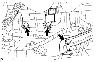
| 26. SEPARATE NO. 3 ENGINE WIRE |
Remove the bolt and separate No. 3 engine wire from the automatic transaxle.
Separate the 2 clamps from the engine mount insulator.
| 27. DISCONNECT CONNECTORS |
Separate the park neutral position switch connector and separate the clamp from the engine mount insulator LH.
Separate the transmission wire connector and separate the clamp from the engine mount insulator.
Separate the transmission revolution sensor connector.
Separate the vehicle speed sensor connector.
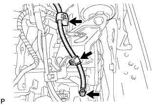
| 28. DISCONNECT WIRE HARNESS |
Remove the 3 bolts and separate the 3 wire harness clamp brackets from the automatic transaxle.
| 29. REMOVE STARTER ASSEMBLY |
Remove the terminal cap.
Remove the nut and remove terminal 30.
Disconnect the connector.
Remove the 2 bolts and remove the starter assembly.
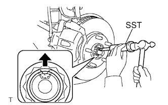
| 30. REMOVE FRONT AXLE HUB NUT LH |
Using SST and a hammer, release the staked part of the axle hub nut.
- SST
- 09930-00010
- NOTICE:
- Insert SST into the groove with the flat surface facing up.
- Do not damage the tip of SST using grinders.
- Completely unstake the staked part before removing the axle hub nut.
- Do not damage the threads of the drive shaft.
Using a 30 mm socket wrench, remove the axle hub nut.
| 31. REMOVE FRONT AXLE HUB NUT RH |
- HINT:
- Use the same procedure for the LH side and RH side.
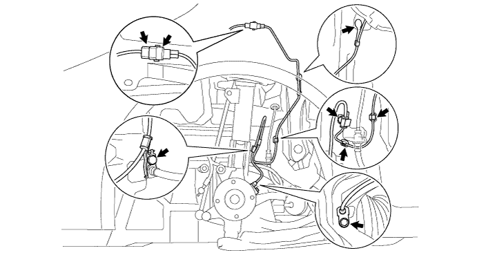
| 32. SEPARATE FRONT SPEED SENSOR LH (w/ ABS) |
Remove the speed sensor clip from the body.
Disconnect the speed sensor connector.
Remove the 3 clips.
Remove the bolt and separate the clamp from the body.
Remove the bolt and separate the clamp from the shock absorber.
Remove the bolt and remove the speed sensor from the steering knuckle.
- NOTICE:
- Keep the speed sensor tip and installation portion free of foreign matter.
- Remove the speed sensor without turning it from its original installation angle.
| 33. SEPARATE FRONT SPEED SENSOR RH (w/ ABS) |
- HINT:
- Use the same procedure for the LH side and RH side.
| 34. SEPARATE FRONT STABILIZER LINK ASSEMBLY LH |
Remove the nut and separate the stabilizer link from the shock absorber.
- HINT:
- If the ball joint turns together with the nut, use a socket hexagon wrench 6 to hold the stud.
| 35. SEPARATE FRONT STABILIZER LINK ASSEMBLY RH |
- HINT:
- Use the same procedure for the LH side and RH side.
| 36. SEPARATE TIE ROD END SUB-ASSEMBLY LH |
Remove the cotter pin and castle nut.
Using SST, separate the tie rod end from the steering knuckle.
- SST
- 09628-62011
- NOTICE:
- Do not damage the tie rod end dust cover.
| 37. SEPARATE TIE ROD END SUB-ASSEMBLY RH |
- HINT:
- Use the same procedure for the LH side and RH side.
| 38. SEPARATE FRONT LOWER SUSPENSION ARM LH |
Remove the clip and castle nut.
Using SST, separate the lower arm.
- SST
- 09628-00011
- NOTICE:
- Do not damage the lower arm dust cover.
- Suspend SST with a piece of string or the equivalent.
Remove the 2 bolts and lower arm.
| 39. SEPARATE FRONT LOWER SUSPENSION ARM RH |
- HINT:
- Use the same procedure for the LH side and RH side.
| 40. SEPARATE FRONT AXLE ASSEMBLY LH |
Using a plastic hammer, tap the end of the drive shaft and disengage the fitting between the drive shaft and front axle.
- HINT:
- If it is difficult to disengage the fitting, tap the end of the drive shaft with a brass bar and hammer.
Push the front axle out of the vehicle to remove the drive shaft from the front axle.
- NOTICE:
- Do not push the front axle further out of the vehicle than is necessary.
- Do not damage the outboard joint boot.
- Do not damage the speed sensor rotor.
- Suspend the drive shaft with a piece of string or the equivalent.
Remove the 2 nuts and 2 bolts and remove the front axle assembly.
- HINT:
- Keep the nut from rotating while turning the bolt.
| 41. SEPARATE FRONT AXLE ASSEMBLY RH |
- HINT:
- Use the same procedure for the LH side and RH side.
| 42. REMOVE AUTOMATIC TRANSMISSION CASE PROTECTOR (w/o ABS) |
Remove the 2 bolts and remove the transmission case protector from the automatic transaxle.
| 43. REMOVE FRONT DRIVE SHAFT ASSEMBLY LH |
Using SST, remove the drive shaft.
- SST
- 09520-01010
09520-24010(09520-32040)
- NOTICE:
- Do not damage the oil seal.
- Do not damage the inboard joint boot.
- Do not drop the drive shaft.
| 44. REMOVE FRONT DRIVE SHAFT ASSEMBLY RH |
Using a screwdriver and hammer, remove the drive shaft.
- NOTICE:
- Do not damage the oil seal.
- Do not damage the inboard joint boot.
- Do not drop the drive shaft.
| 45. SUSPEND ENGINE ASSEMBLY |
Remove the bolt and remove the radio setting condenser.
Remove the bolt and remove the air-fuel ratio sensor wiring bracket.
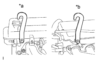
Install the engine hanger with the bolt in the position shown in the illustration.
Text in Illustration*a
| Front Side
|
*b
| Rear Side
|
Part No.Engine Hanger
| 12281-21010
|
Bolt
| 91642-81025
|
- Torque:
- 40 N*m{408 kgf*cm, 30 ft.*lbf}
Using an engine sling device and a chain block, support the engine assembly w/transaxle and front suspension crossmember.
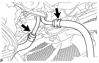
| 46. SEPARATE INLET OIL COOLER HOSE |
Separate the inlet oil cooler hose from inlet No. 1 oil cooler tube.
| 47. SEPARATE OUTLET OIL COOLER HOSE |
Separate the outlet oil cooler hose from outlet No. 1 oil cooler tube.
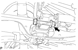
| 48. SEPARATE ENGINE MOVING CONTROL ROD |
Remove the bolt and nut and separate the engine moving control rod from the bracket.
| 49. REMOVE FRONT SUSPENSION CROSSMEMBER SUB-ASSEMBLY |
Remove the bolt and separate the engine moving control rod.
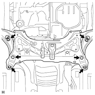
Place wooden blocks or plate lift attachments in the positions shown in the illustration and set an engine lifter underneath the front suspension crossmember.
Text in Illustration
| Front of the Vehicle
|

| Attachment Placement Positions
|
- NOTICE:
- Place the wooden blocks or plate lift attachments so that the front suspension crossmember sub-assembly is level.
- As the front suspension crossmember subassembly is very heavy, be sure to support it securely.
Remove the 6 bolts and front suspension crossmember sub-assembly.
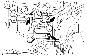
| 50. REMOVE ENGINE MOVING CONTROL ROD BRACKET |
Remove the 3 bolts and remove the engine moving control rod bracket.
| 51. SUPPORT AUTOMATIC TRANSAXLE ASSEMBLY |
Support the automatic transmission with the transmission jack.
| 52. SEPARATE ENGINE MOUNTING INSULATOR LH |
Remove the bolt and nut and separate the engine mounting insulator LH from the bracket.
| 53. REMOVE ENGINE MOUNTING BRACKET LH |
Remove the 4 bolts and remove the engine mounting bracket LH from the automatic transaxle.
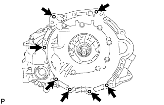
| 54. REMOVE AUTOMATIC TRANSAXLE ASSEMBLY |
Remove the flywheel housing under cover.
Remove the 6 torque converter set bolts while holding the crankshaft pulley bolt with a wrench.
Remove the 7 bolts and remove the automatic transmission from the engine.
| 55. REMOVE TORQUE CONVERTER CLUTCH ASSEMBLY |
Remove the torque converter clutch from the automatic transaxle.
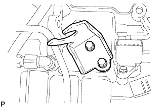
| 56. REMOVE NO. 1 TRANSMISSION CONTROL CABLE BRACKET |
Remove the 2 bolts and remove No. 1 transmission control cable bracket from the automatic transaxle.
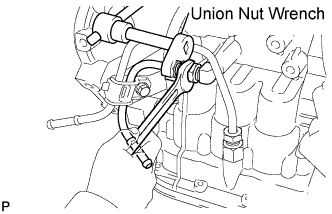
| 57. SEPARATE INLET NO. 1 OIL COOLER TUBE |
Using a union nut wrench, separate the inlet No. 1 oil cooler tube while holding the oil cooler tube union with a wrench.
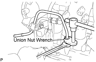
| 58. SEPARATE OUTLET NO. 1 OIL COOLER TUBE |
Using a union nut wrench, separate the outlet No. 1 oil cooler tube while holding the oil cooler tube union with a wrench.
| 59. REMOVE NO. 2 OIL COOLER TUBE CLAMP |
Remove the bolt and remove No. 2 oil cooler tube clamp from the oil filler tube.
Remove the inlet oil cooler tube and the outlet oil cooler tube from the automatic transaxle.
| 60. REMOVE TRANSMISSION OIL LEVEL GAUGE SUB-ASSEMBLY |
Remove the oil level gauge from the oil filler tube.
| 61. REMOVE TRANSMISSION OIL FILLER TUBE SUB-ASSEMBLY |
Remove the bolt and remove the oil filler tube.
Remove the O-ring from the oil filler tube.