Transmission Control Cable (For Sedan) -- Installation |
| 1. INSTALL TRANSMISSION CONTROL CABLE ASSEMBLY |
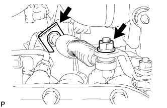 |
Install the control cable onto the control shaft lever with the nut.
- Torque:
- 12 N*m{122 kgf*cm, 9 ft.*lbf}
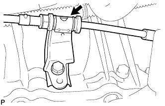
Fix the control cable onto the control cable bracket with a new clip.
Connect the control cable to the clamp.
 |
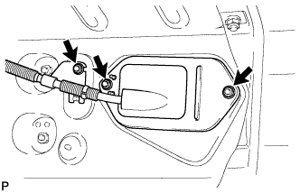
Install the control cable with the 3 nuts.
- Torque:
- 5.0 N*m{51 kgf*cm, 44 in.*lbf}
 |
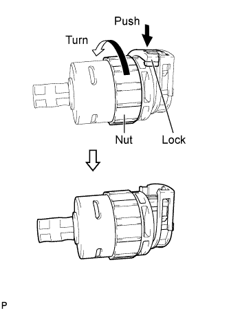
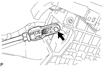
Turn the nut of the control cable and push in the lock.
 |
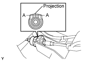
Install the control cable onto the shift lever retainer.
- NOTICE:
- Install the cable with the protruding portion of the cable outer facing upward.
- After installing, check that the lock of the cable outer is protruding beyond portion A-A, as shown in the illustration.
 |
Connect the control cable to the shift lever.
- NOTICE:
- Connect the control cable so that the adjusting mechanism lock of the control cable is installed on the left side of the vehicle.
 |
| 2. INSTALL FRONT NO. 1 FLOOR HEAT INSULATOR |
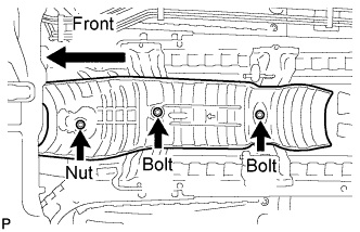 |
Install floor heat insulator with the 2 bolts and the nut.
- Torque:
- 5.5 N*m{56 kgf*cm, 49 in.*lbf}
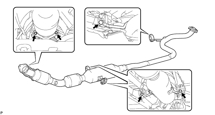
| 3. INSTALL FRONT EXHAUST PIPE ASSEMBLY |
 |
Using vernier calipers, measure the free length of the compression spring.
- Minimum length (Front side):
- 40.5 mm (1.594 in.)
- Minimum length (Rear side):
- 38.5 (1.516 in.)
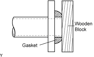
Using a plastic hammer and a wooden block, tap in a new exhaust pipe gasket until its surface is flush with the front exhaust pipe assembly.
- NOTICE:
- Install the exhaust pipe gasket in the correct direction.
- Do not damage the outer surface of the exhaust pipe gasket.
- Do not reuse the exhaust pipe gasket.
- Do not push in the gasket with the exhaust pipe when connecting it.
 |
Install the 3 No. 4 exhaust pipe supports and front exhaust pipe assembly.
Install the exhaust front pipe assembly and a new exhaust pipe gasket with the 4 compression springs and 4 bolts.
- Torque:
- 43 N*m{438 kgf*cm, 32 ft.*lbf}
| 4. CONNECT OXYGEN SENSOR CONNECTOR |
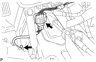 |
Insert the oxygen sensor connector toward the room side, through the hole in the floor panel, and then install the grommet.
Connect the oxygen sensor connector.
| 5. INSTALL AIR CLEANER BRACKET |
Install the air cleaner bracket with the 2 bolts.
- Torque:
- 19 N*m{194 kgf*cm, 14 ft.*lbf}
Connect the wire harness clamp to the air cleaner bracket.
| 6. INSTALL AIR CLEANER ASSEMBLY |
Install the air cleaner case with air cleaner inlet No. 1 with the 2 bolts.
- Torque:
- 7.8 N*m{80 kgf*cm, 69 in.*lbf}
Connect the wire harness to the air cleaner case.
Install the air cleaner element.
Install and lock the air cleaner cap and the air cleaner hose and then tighten the air cleaner hose clamp.
- Torque:
- 4.0 N*m{41 kgf*cm, 35 in.*lbf}
Connect the ventilation hose to the air cleaner hose.
Connect the vacuum switching valve connector and the wire harness clamp.
Connect the fuel vapor feed hose to the vacuum switching valve assembly and air cleaner hose.
Connect the intake air flow meter connector and the wire harness clamp.
| 7. INSTALL BATTERY TRAY |
| 8. INSTALL BATTERY |
Install the battery onto the vehicle with the battery clamp.
- Torque:
- 3.5 N*m{36 kgf*cm, 31 in.*lbf}
Connect the cable to the battery terminal.
- Torque:
- 5.4 N*m{55 kgf*cm, 48 in.*lbf}
| 9. INSPECT SHIFT LEVER POSITION |
When shifting the lever from P to the R position with the ignition switch ON and the brake pedal depressed, make sure that the shift lever moves smoothly and moves correctly into position.
Start the engine and make sure that the vehicle moves forward when shifting the lever from N to the D position and moves rearward when shifting the lever to the R position.
If the operation cannot be performed as specified, inspect the park/neutral position switch assembly and check the shift lever assembly installation condition.
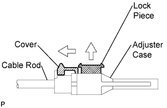
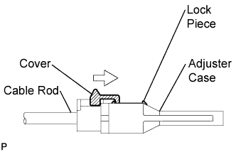
| 10. ADJUST SHIFT LEVER POSITION |
Shift the shift lever to the N position.
Slide the adjuster case cover in the direction shown in the illustration and pull out the lock piece.
 |
Gently pull the cable rod toward the rear of the vehicle by hand to pull the cable taut.
Press the lock piece into the adjuster case and lock it.
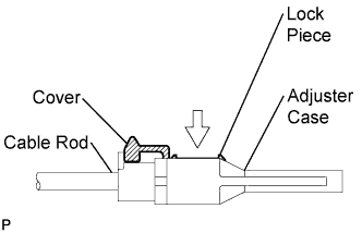 |
Slide the cover in the direction shown in the illustration.
- NOTICE:
- Slide the cover past the protrusion of the lock piece.
 |
Inspect the operation after the adjustment.
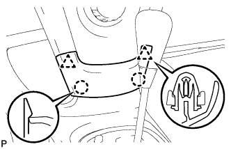
| 11. INSTALL REAR CONSOLE BOX ASSEMBLY |
Engage the 4 claws and install the rear console box.
 |
Install the 2 bolts and 2 screws.
Connect the clamp.
| 12. INSTALL CONSOLE BOX CARPET |
Install the console box carpet.
 |
| 13. INSTALL REAR UPPER CONSOLE PANEL SUB-ASSEMBLY |
 |
Connect the connector.
Engage the 3 clips and 3 claws and install the rear upper console panel.
| 14. INSTALL UPPER CONSOLE PANEL SUB-ASSEMBLY |
 |
Engage the 5 clips and the claw and install the upper console panel.
| 15. INSTALL CENTER LOWER INSTRUMENT PANEL FINISH PANEL |
 |
Engage the 2 claws and 2 clips and install the instrument panel finish panel.
| 16. CHECK FOR EXHAUST GAS LEAKAGE |