INSTALL INSTRUMENT CLUSTER CENTER FINISH PANEL SUB-ASSEMBLY (except Integrated with Panel)
INSTALL LUGGAGE COMPARTMENT TRIM INNER PAD (for 60/40 Split Seat Type)
INSTALL SPARE WHEEL COVER ASSEMBLY (for 60/40 Split Seat Type)
INSTALL LUGGAGE COMPARTMENT FLOOR MAT (for 60/40 Split Seat Type)
INSTALL REAR SEATBACK ASSEMBLY RH (for 60/40 Split Seat Type)
INSTALL REAR SEATBACK ASSEMBLY LH (for 60/40 Split Seat Type)
Radio Antenna Cord (For Sedan) -- Installation |
- CAUTION:
- Some of these service operations affect the SRS airbag system. Read the precautionary notices concerning the SRS airbag system before servicing (YARIS_NCP93 RM000000KT10D1X.html).
| 1. INSTALL NO. 2 ANTENNA CORD SUB-ASSEMBLY |
w/ Curtain Shield Airbag:
Install the antenna cord positioning tapes into the 4 claws of the front and rear side rail spacers.
Align the antenna cord positioning tapes with the markings on the roof headlining.
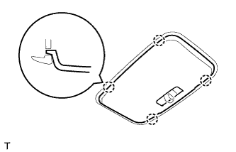
Install the antenna cord onto the roof headlining with 8 new pieces of tape.

Tape size: Mark Measurement a 80 mm (3.15 in.) b 20 mm (0.787 in.) - NOTICE:
- Apply the tape securely in place.
- Do not touch the adhesive surface when applying the tape to prevent adhesion failure.
w/o Curtain Shield Airbag:
Install the antenna cord positioning tapes into the 6 claws of the front and rear side rail spacers.
Align the antenna cord positioning tapes with the markings on the roof headlining.
Install the antenna cord onto the roof headlining with 6 new pieces of tape.
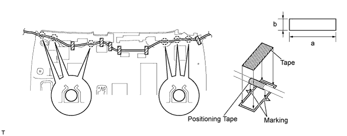
Tape size: Mark Measurement a 80 mm (3.15 in.) b 20 mm (0.787 in.) - NOTICE:
- Apply the tape securely in place.
- Do not touch the adhesive surface when applying the tape to prevent adhesion failure.
| 2. INSTALL ROOF HEADLINING ASSEMBLY |
w/ Curtain Shield Airbag:
Engage the 4 hooks and install the roof headlining.
Install the 2 clips.
 |
w/o Curtain Shield Airbag:
Engage the 2 claws and 4 hooks and install the roof headlining.
Install the 2 clips.
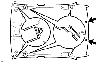 |
Connect the antenna connector.
 |
Install the clamp.
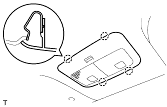
| 3. INSTALL MAP LIGHT ASSEMBLY |
Connect the map light connector.
 |
Engage the 4 claws and install the map light.
 |
| 4. INSTALL ROOM LIGHT ASSEMBLY |
Engage the 4 claws and install the room light switch base.
 |
Install the roof wire into the claw of the room light.
Engage the 4 claws and install the room light.
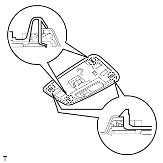 |
Engage the 2 claws and install the cover.
- HINT:
- Use the same procedure for both sides.
 |
Engage the 4 claws and install the room light lens.
 |
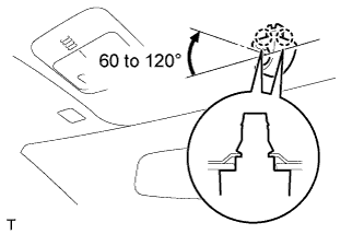
| 5. INSTALL VISOR HOLDER RH |
Engage the 2 claws by turning the visor holder clockwise between 60 to 120° and install the visor holder.
 |
| 6. INSTALL VISOR HOLDER LH |
- HINT:
- Use the same procedure as for the RH side.
| 7. INSTALL VISOR ASSEMBLY RH |
Engage the 2 springs and install the visor.
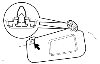 |
Install the visor shaft into the visor holder.
Engage the 4 claws and install a new visor bracket cover.
 |
| 8. INSTALL VISOR ASSEMBLY LH |
- HINT:
- Use the same procedure as for the RH side.
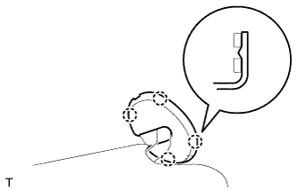
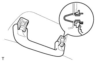
| 9. INSTALL ASSIST GRIP SUB-ASSEMBLY |
 |
- HINT:
- Use the same procedure to install all the assist grips.
Engage the 2 springs and install the assist grip.
 |
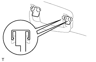
| 10. INSTALL ASSIST GRIP COVER |
 |
- HINT:
- Use the same procedure to install all the assist grip covers.
Engage the 2 claws and install the assist grip cover.
 |
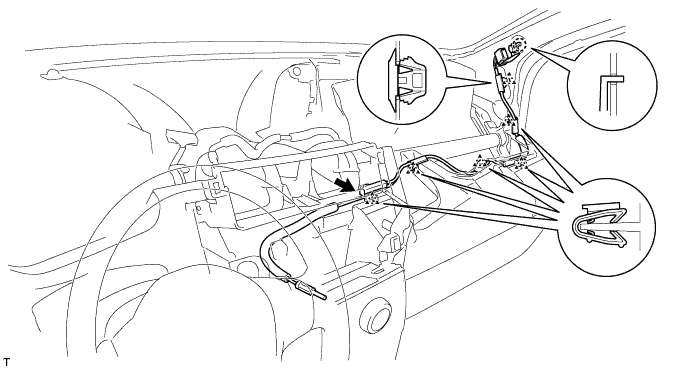
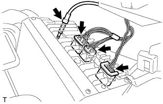
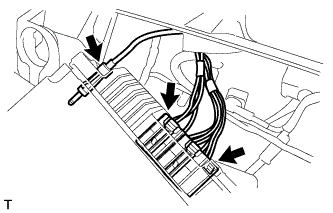
| 11. INSTALL ANTENNA CORD SUB-ASSEMBLY |
Install the antenna cord with the 5 clamps.
Connect the antenna amplifier connector.
Insert the hook into the body hole and install the bracket with the bolt.
| 12. INSTALL RADIO RECEIVER ASSEMBLY |
for Integrated with Panel:
Connect the plug.
Connect the 3 radio connectors.
Align the 2 bosses of the instrument panel with the hole in the radio bracket.
Engage the 4 clips and 4 claws and install the radio receiver.
Tighten the 4 bolts.
Connect the hazard warning signal switch connector.

 |
except Integrated with Panel:
Connect the plug.
Connect the 2 radio connectors.
Align the 2 bosses of the instrument panel with the hole in the radio bracket.
Install the radio receiver with the 4 bolts.

 |
| 13. INSTALL INSTRUMENT CLUSTER CENTER FINISH PANEL SUB-ASSEMBLY (except Integrated with Panel) |
 |
Engage the 2 claws and 4 clips and install the instrument cluster finish panel center.
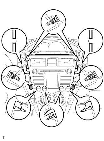
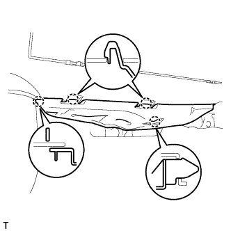
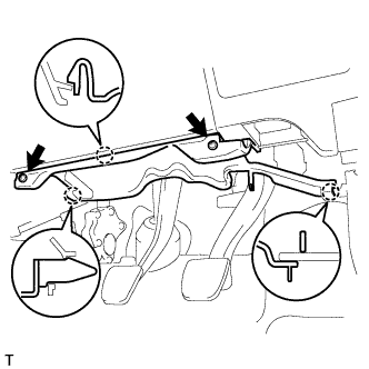
| 14. INSTALL UPPER INSTRUMENT PANEL SUB-ASSEMBLY |
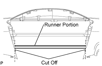 |
Using a nipper, cut off both ends of the runner portion shown in the illustration (When installing a new one).
Engage the 5 claws at the front side of the instrument panel.
Engage the 7 clips at the rear side of the instrument panel.
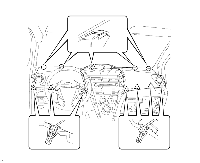
Install the upper instrument panel with the 2 <C> bolts and the 2 <B> screws.
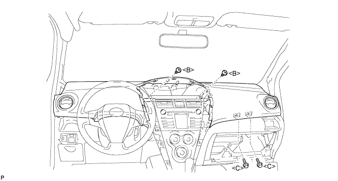
- Torque:
- 20 N*m{204 kgf*cm, 15 ft.*lbf} for bolt <C>
Connect the passenger airbag connector and clamp.
 |
| 15. INSTALL GLOVE COMPARTMENT DOOR ASSEMBLY |
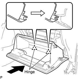 |
Engage the claws of the hinge portions by pushing the glove compartment door in the horizontal direction to install the glove compartment door assembly.
- NOTICE:
- Engage the claw by pushing it in the horizontal direction, otherwise, installation failure caused by excessive play around the hinge portion will result.
Slightly flex the upper portion of the glove compartment door assembly to engage the stopper.
 |
Install the 2 glove compartment door stoppers onto the glove compartment door.
| 16. INSTALL COMBINATION METER ASSEMBLY |
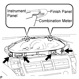 |
Install the combination meter assembly with the 2 screws.
- NOTICE:
- Install the meter by inserting the ribbed portions of the meter between the instrument panel and meter cluster.
Connect the 2 connectors.
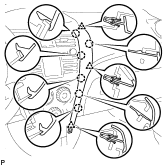
| 17. INSTALL INSTRUMENT CLUSTER FINISH PANEL NO.1 |
 |
Fit the 2 claws of the instrument cluster finish panel into the upper instrument cluster finish panel center.
Engage the 5 claws and 5 clips and install the instrument cluster finish panel.
 |
| 18. INSTALL INSTRUMENT PANEL FINISH PANEL END RH |
 |
Engage the 6 claws and 3 clips and install the instrument panel finish panel end RH.
| 19. INSTALL INSTRUMENT PANEL FINISH PANEL END LH |
 |
Engage the 6 claws and 3 clips and install the instrument panel finish panel end LH.
| 20. INSTALL INSTRUMENT PANEL LOWER CENTER FINISH PANEL |
 |
Engage the 2 claws and 2 clips and install the instrument panel finish panel lower center.
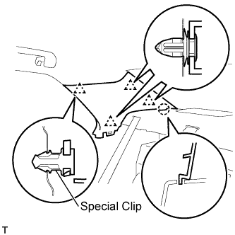
| 21. INSTALL FRONT PILLAR GARNISH RH |
w/ Curtain Shield Airbag:
Remove the piece of cloth or nylon.
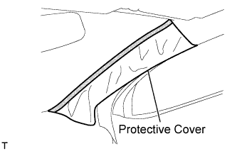 |
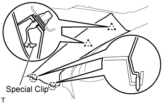
Install the 3 clamps.
 |
Connect the antenna connector.
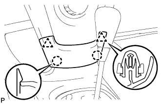
w/ Curtain Shield Airbag:
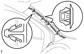
Install 2 new special clips and the clip onto the front pillar garnish.
Engage the 2 clips and the 2 claws and install the front pillar garnish.
 |
w/o Curtain Shield Airbag:
Engage the 2 clips and the 2 claws and install the front pillar garnish.
 |
| 22. INSTALL FRONT PILLAR GARNISH LH |
w/ Curtain Shield Airbag:
Remove the piece of cloth or nylon.
 |
Install the 4 clamps.
 |
w/ Curtain Shield Airbag:
Install 2 new special clips and the clip onto the front pillar garnish.
Engage the 2 clips and the 2 claws and install the front pillar garnish.
 |
w/o Curtain Shield Airbag:
Engage the 2 clips and the 2 claws and install the front pillar garnish.
 |
| 23. INSTALL CENTER PILLAR UPPER GARNISH RH |
Engage the 2 hooks and 2 clips and install the center pillar upper garnish.
 |
| 24. INSTALL CENTER PILLAR UPPER GARNISH LH |
- HINT:
- Use the same procedure as for the RH side.
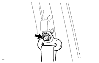
| 25. INSTALL FRONT SEAT OUTER BELT ASSEMBLY RH |
Install the through anchor with the bolt.
- Torque:
- 42 N*m{430 kgf*cm, 31 ft.*lbf}
 |
| 26. INSTALL FRONT SEAT OUTER BELT ASSEMBLY LH |
- HINT:
- Use the same procedure as for the RH side.
| 27. INSTALL SEAT BELT ANCHOR COVER CAP |
 |
- HINT:
- Use the same procedure for both sides.
Engage the 3 claws and install the seat belt anchor cover cap.
| 28. INSTALL CENTER PILLAR LOWER GARNISH RH |
Engage the 2 clips and 3claws and install the center pillar lower garnish.
 |
| 29. INSTALL CENTER PILLAR LOWER GARNISH LH |
- HINT:
- Use the same procedure as for the RH side.
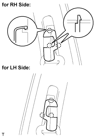
| 30. INSTALL ROOF SIDE INNER GARNISH RH |
w/ Curtain Shield Airbag:
Install a new special clip and the clip onto the roof side inner garnish.
Engage the 4 clips and the claw and install the roof side inner garnish.
 |
w/o Curtain Shield Airbag:
Engage the 4 clips and the claw and install the roof side inner garnish.
 |
| 31. INSTALL ROOF SIDE INNER GARNISH LH |
- HINT:
- Use the same procedure as for the RH side.
| 32. INSTALL REAR SEAT SIDE COVER RH |
Engage the 2 clips and the 4 claws and install the rear seat side cover.
 |
| 33. INSTALL REAR SEAT SIDE COVER LH |
- HINT:
- Use the same procedure as for the RH side.
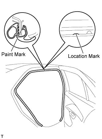
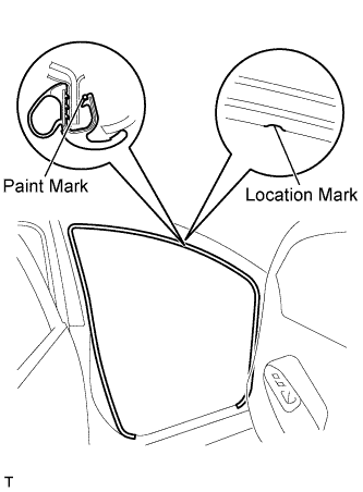
| 34. INSTALL REAR DOOR OPENING TRIM WEATHERSTRIP RH |
Align the location mark with the paint mark first, and install the rear door opening trim weatherstrip, as shown in the illustration.
- Paint mark:
Area Color RH side Green LH side Red
 |
| 35. INSTALL REAR DOOR OPENING TRIM WEATHERSTRIP LH |
- HINT:
- Use the same procedure as for the RH side.
| 36. INSTALL REAR DOOR SCUFF PLATE RH |
Engage the 7 claws and install the rear door scuff plate.
 |
| 37. INSTALL REAR DOOR SCUFF PLATE LH |
- HINT:
- Use the same procedure as for the RH side.
| 38. INSTALL FRONT DOOR OPENING TRIM WEATHERSTRIP RH |
Align the location mark with the paint mark first, and install the front door opening trim weatherstrip, as shown in the illustration.
- Paint mark:
Area Color RH side Blue LH side Pink
 |
| 39. INSTALL FRONT DOOR OPENING TRIM WEATHERSTRIP LH |
- HINT:
- Use the same procedure as for the RH side.
| 40. INSTALL COWL SIDE TRIM BOARD RH |
Engage the stud bolt and the claw and install the cowl side trim board.
 |
| 41. INSTALL COWL SIDE TRIM BOARD LH |
- HINT:
- Use the same procedure as for the RH side.
| 42. INSTALL INSTRUMENT PANEL UNDER COVER SUB-ASSEMBLY RH |
Engage the 4 claws and install the instrument panel under cover.
 |
| 43. INSTALL INSTRUMENT PANEL UNDER COVER SUB-ASSEMBLY LH |
Engage the 3 claws and install the instrument panel under cover.
 |
Tighten the 2 screws.
| 44. INSTALL FRONT DOOR SCUFF PLATE RH |
Engage the 11 claws and install the front door scuff plate.
 |
| 45. INSTALL FRONT DOOR SCUFF PLATE LH |
- HINT:
- Use the same procedure as for the RH side.
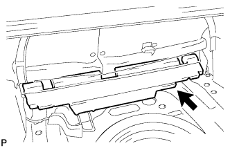
| 46. INSTALL LUGGAGE COMPARTMENT TRIM INNER PAD (for 60/40 Split Seat Type) |
 |
w/ Grand Spare Tire:
Install the luggage compartment trim inner pad.
w/o Grand Spare Tire:
Install the luggage compartment trim inner pad.
 |
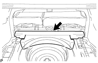
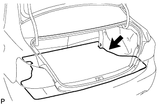
| 47. INSTALL SPARE WHEEL COVER ASSEMBLY (for 60/40 Split Seat Type) |
 |
Install the spare wheel cover.
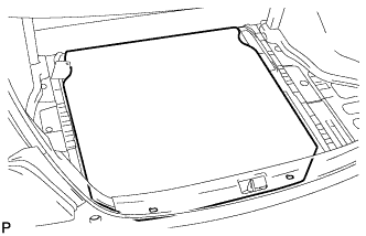
| 48. INSTALL LUGGAGE COMPARTMENT FLOOR MAT (for 60/40 Split Seat Type) |
 |
Install the luggage compartment floor mat.
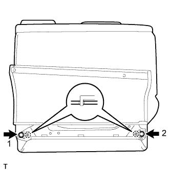
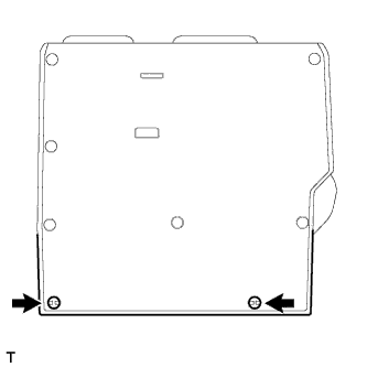
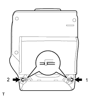
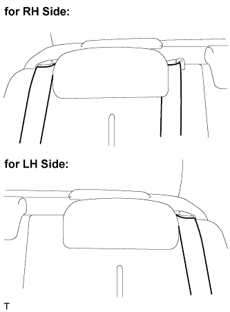
| 49. INSTALL REAR SEATBACK ASSEMBLY RH (for 60/40 Split Seat Type) |
Insert the 2 hooks into the rear seatback frame hole and install the rear seatback, tightening the 2 bolts in the sequence shown in the illustration.
- Torque:
- 37 N*m{375 kgf*cm, 27 ft.*lbf}
 |
Install the rear seatback cover with the 2 clips.
 |
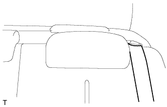
Pull up the rear seatback.
Install the rear seat outer belt into the rear seat shoulder belt guide.
 |
Install the rear center seat outer belt into the rear center seat shoulder belt guide.
| 50. INSTALL REAR SEATBACK ASSEMBLY LH (for 60/40 Split Seat Type) |
Insert the 2 hooks into the rear seatback frame hole and install the rear seatback, tightening the 2 bolts in the sequence shown in the illustration.
- Torque:
- 37 N*m{375 kgf*cm, 27 ft.*lbf}
 |
Install the rear seatback cover with the 2 clips.
 |
Pull up the rear seatback.
Install the rear seat outer belt into the rear seat shoulder belt guide.
 |
| 51. INSTALL REAR SEATBACK ASSEMBLY (for Fixed Seat Type) |
Engage the 3 hooks and install the rear seatback.
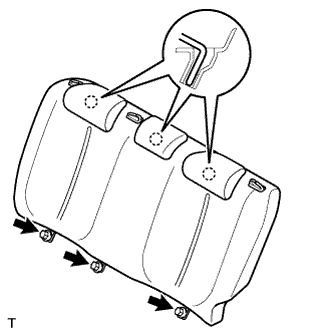 |
Tighten the 3 bolts.
- Torque:
- 7.9 N*m{80 kgf*cm, 70 in.*lbf}
Install the rear seat outer belt into the rear seat shoulder belt guide.
- HINT:
- Use the same procedure for both sides.
 |
Install the rear center seat outer belt into the rear center seat shoulder belt guide.
| 52. INSTALL REAR SEAT CUSHION COVER PAD SUB-ASSEMBLY |
for 60/40 Split Seat Type:
Install the rear seat cushion cover pad sub-assembly (YARIS_NCP93 RM0000026GB00WX_01_0003.html).
for Fixed Seat Type:
Install the rear seat cushion cover pad sub-assembly (YARIS_NCP93 RM000001GLY00YX_02_0014.html).
| 53. CONNECT CABLE TO NEGATIVE BATTERY TERMINAL |
- Torque:
- 5.4 N*m{55 kgf*cm, 48 in.*lbf}
| 54. INSPECT SRS WARNING LIGHT |