Theft Deterrent System (For Sedan) Unlock Warning Switch Circuit
DESCRIPTION
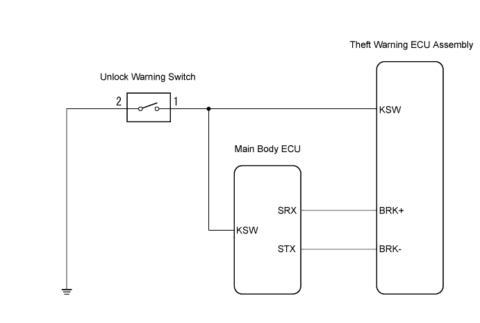
WIRING DIAGRAM
INSPECTION PROCEDURE
CHECK FOR DTC
READ VALUE USING TECHSTREAM (UNLOCK WARNING SWITCH)
INSPECT UNLOCK WARNING SWITCH ASSEMBLY
CHECK HARNESS AND CONNECTOR (THEFT WARNING ECU ASSEMBLY - UNLOCK WARNING SWITCH ASSEMBLY)
CHECK HARNESS AND CONNECTOR (UNLOCK WARNING SWITCH ASSEMBLY - BODY GROUND)
THEFT DETERRENT SYSTEM (for Sedan) - Unlock Warning Switch Circuit |
DESCRIPTION
The key unlock warning switch comes on when the ignition key is inserted into the ignition key cylinder and goes off when the ignition key is removed.The theft warning ECU operates the key confinement prevention function while the key unlock warning switch is on.
WIRING DIAGRAM
INSPECTION PROCEDURE
Connect the Techstream to the DLC3.
Turn the ignition switch to ON and turn the tester ON.
Clear the DTCs.
Check whether DTC B1269 recurs 10 seconds or more after the ignition switch is turned ON.
- OK:
- No DTC is output.
| 2.READ VALUE USING TECHSTREAM (UNLOCK WARNING SWITCH) |
Connect the Techstream to the DLC3.
Turn the ignition switch to ON.
Turn the tester main switch ON.
Select the item below in the Data List and then read the display on the tester.
- Theft Warning ECU:
Item
| Measurement Item/Display (Range)
| Normal Condition
| Diagnostic Note
|
Key SW
| Unlock warning switch signal ON/OFF
| ON: Key is inserted into ignition key cylinder
OFF: Key is removed from ignition key cylinder
| -
|
- OK:
- When the key is in the ignition key cylinder, "ON" appears on the screen.
| OK |
|
|
|
| PROCEED TO NEXT CIRCUIT INSPECTION SHOWN IN PROBLEM SYMPTOMS TABLE |
|
| 3.INSPECT UNLOCK WARNING SWITCH ASSEMBLY |
Remove the unlock warning switch assembly.
Measure the resistance.
- Standard resistance:
Tester Connection
| Condition
| Specified Condition
|
1 - 2
| Pushed
(ON (Key inserted))
| Below 1 Ω
|
1 - 2
| Not pushed
(OFF (Key removed))
| 10 kΩ or higher
|
Reinstall the unlock warning switch assembly.
| 4.CHECK HARNESS AND CONNECTOR (THEFT WARNING ECU ASSEMBLY - UNLOCK WARNING SWITCH ASSEMBLY) |
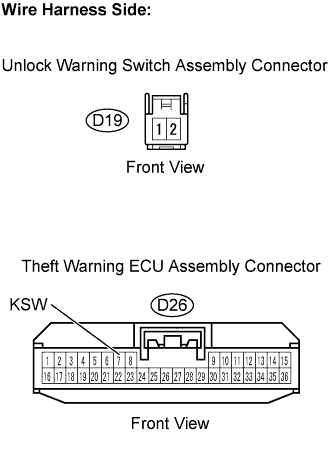
Disconnect the D26 theft warning ECU and the D19 unlock warning switch connectors.
Measure the resistance.
- Standard resistance:
Tester Connection
| Specified Condition
|
D26-7 (KSW) - (D19-1)
| Below 1 Ω
|
D26-7 (KSW) - Body ground
| 10 kΩ or higher
|
Reconnect the theft warning ECU and the unlock warning switch connectors.
| | REPAIR OR REPLACE HARNESS OR CONNECTOR |
|
|
| 5.CHECK HARNESS AND CONNECTOR (UNLOCK WARNING SWITCH ASSEMBLY - BODY GROUND) |
Disconnect the D19 unlock warning switch connector.
Measure the resistance.
- Standard resistance:
Tester Connection
| Specified Condition
|
D19-2 - Body ground
| Below 1 Ω
|
Reconnect the unlock warning switch connector.
| | REPAIR OR REPLACE HARNESS OR CONNECTOR |
|
|