Power Window Control System (For Hatchback) -- Terminals Of Ecu |
| POWER WINDOW REGULATOR MASTER SWITCH ASSEMBLY |

Disconnect the G20 power window regulator master switch assembly connector.
Measure the voltage and resistance according to the value(s) in the table below.
w/ Rear Power Window Terminal No. (Symbol) Wiring Color Terminal Description Condition Specified Condition G20-6 (B) - G20-1 (E) GR - W-B Power supply Ignition switch ON 11 to 14 V G20-1 (E) - Body ground W-B - Body ground Ground Always Below 1 Ω
If the result is not as specified, there may be a malfunction in the wire harness.w/o Rear Power Window Terminal No. (Symbol) Wiring Color Terminal Description Condition Specified Condition G20-15 (B) - G20-7 (E) GR - W-B Power supply Ignition switch ON 11 to 14 V G20-7 (E) - Body ground W-B - Body ground Ground Always Below 1 Ω Reconnect the power window regulator master switch assembly connector.
Measure the voltage according to the value(s) in the table below.
w/ Rear Power Window Terminal No. (Symbol) Wiring Color Terminal Description Condition Specified Condition G20-3 (U) - G20-1 (E) LA-R - W-B Power window motor UP operation Ignition switch ON, driver door power window switch OFF → UP 11 to 14 V → Below 1 V G20-4 (D) - G20-1 (E) LA-G - W-B Power window motor DOWN operation Ignition switch ON, driver door power window switch OFF → DOWN (Manual operation) 11 to 14 V → Below 1 V Power window motor AUTO DOWN operation Ignition switch ON, driver side door glass fully closed → driver side power window AUTO DOWN operation → driver side door glass fully opened 11 to 14 V → Below 1 V → 11 to 14 V
If the result is not as specified, the power window regulator master switch assembly may have a malfunction.w/o Rear Power Window Terminal No. (Symbol) Wiring Color Terminal Description Condition Specified Condition G20-10 (U) - G20-7 (E) LA-R - W-B Power window motor UP operation Ignition switch ON, driver door power window switch OFF → UP (Manual operation) 11 to 14 V → Below 1 V G20-12 (D) - G20-7 (E) LA-G - W-B Power window motor DOWN operation Ignition switch ON, driver door power window switch OFF → DOWN (Manual operation) 11 to 14 V → Below 1 V Power window motor AUTO DOWN operation Ignition switch ON, driver side door glass fully closed → driver side power window AUTO DOWN operation → driver side door glass fully opened 11 to 14 V → Below 1 V → 11 to 14 V
| CHECK POWER WINDOW REGULATOR SWITCH ASSEMBLY (FRONT PASSENGER SIDE) |

Disconnect the F20 power window regulator switch assembly (front passenger side) connector.
Measure the voltage and resistance according to the value(s) in the table below.
If the result is not as specified, there may be a malfunction in the wire harness.Terminal No. (Symbol) Wiring Color Terminal Description Condition Specified Condition F20-3 (B) - Body ground L - Body ground Power supply Ignition switch ON 11 to 14 V F20-5 (SU) - Body ground W - Body ground Ground Always Below 1 Ω F20-2 (SD) - Body ground P - Body ground Ground Always Below 1 Ω Reconnect the F20 power window regulator switch assembly (front passenger side) connector.
Measure the voltage according to the value(s) in the table below.
If the result is not as specified, the power window regulator switch assembly (front passenger side) may have a malfunction.Terminal No. (Symbol) Wiring Color Terminal Description Condition Specified Condition F20-4 (U) - Body ground LA-R - Body ground Power window motor UP operation Front passenger side power window switch OFF → UP Below 1 V → 11 to 14 V F20-1 (D) - Body ground LA-G - Body ground Power window motor DOWN operation Front passenger side power window switch OFF → DOWN Below 1 V → 11 to 14 V
| CHECK REAR POWER WINDOW REGULATOR SWITCH ASSEMBLY LH |

Disconnect the H10 rear power window regulator switch assembly LH connector.
Measure the voltage and resistance according to the value(s) in the table below.
Terminal No. (Symbol) Wiring Color Terminal Description Condition Specified Condition H10-3 (B) - Body ground LA-SB - Body ground Power supply Ignition switch ON 11 to 14 V H10-5 (SU) - Body ground LA-R - Body ground Ground Always Below 1 Ω H10-2 (SD) - Body ground LA-G - Body ground Ground Always Below 1 Ω Reconnect the H10 rear power window regulator switch assembly LH connector.
Measure the voltage according to the value(s) in the table below.
If the result is not as specified, the rear power window regulator switch assembly LH may have a malfunction.Terminal No. (Symbol) Wiring Color Terminal Description Condition Specified Condition H10-4 (U) - Body ground LA-Y - Body ground Power window motor UP operation Front passenger side power window switch OFF → UP Below 1 V → 11 to 14 V H10-1 (D) - Body ground LA-B - Body ground Power window motor DOWN operation Front passenger side power window switch OFF → DOWN Below 1 V → 11 to 14 V
| CHECK REAR POWER WINDOW REGULATOR SWITCH ASSEMBLY RH |

Disconnect the R1 rear power window regulator switch assembly RH connector.
Measure the voltage and resistance according to the value(s) in the table below.
Terminal No. (Symbol) Wiring Color Terminal Description Condition Specified Condition R1-3 (B) - Body ground LA-SB - Body ground Power supply Ignition switch ON 11 to 14 V R1-5 (SU) - Body ground LA-R - Body ground Ground Always Below 1 Ω R1-2 (SD) - Body ground LA-G - Body ground Ground Always Below 1 Ω Reconnect the R1 rear power window regulator switch assembly RH connector.
Measure the voltage according to the value(s) in the table below.
If the result is not as specified, the rear power window regulator switch assembly RH may have a malfunction.Terminal No. (Symbol) Wiring Color Terminal Description Condition Specified Condition R1-4 (U) - Body ground LA-Y - Body ground Power window motor UP operation Front passenger side power window switch OFF → UP Below 1 V → 11 to 14 V R1-1 (D) - Body ground LA-B - Body ground Power window motor DOWN operation Front passenger side power window switch OFF → DOWN Below 1 V → 11 to 14 V
| CHECK INSTRUMENT PANEL JUNCTION BLOCK ASSEMBLY AND MAIN BODY ECU |
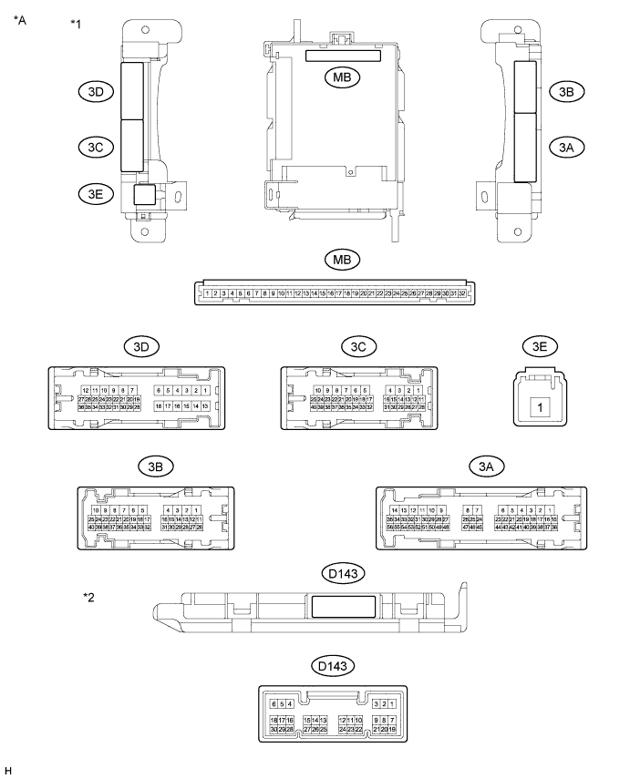
| *A | Main Body ECU 1 Connector Type | - | - |
| *1 | Instrument Panel Junction Block Assembly | *2 | Main Body ECU |
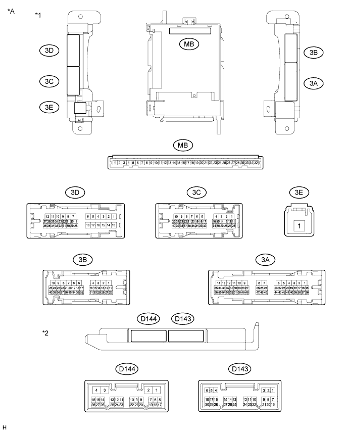
| *A | Main Body ECU 2 Connector Type | - | - |
| *1 | Instrument Panel Junction Block Assembly | *2 | Main Body ECU |
Remove the main body ECU.
Measure the voltage and resistance according to the value(s) in the table below.
If the result is not as specified, there may be a malfunction in the wire harness.Terminal No. (Symbol) Wiring Color Terminal Description Condition Specified Condition MB-11 (GND1) - Body ground - Ground Always Below 1 Ω MB-29 (ACC) - Body ground - Ignition power supply (ACC signal) Ignition switch ACC 11 to 14 V MB-30 (BECU) - Body ground - Battery power supply Always 11 to 14 V MB-32 (IG) - Body ground - Ignition power supply (IG signal) Ignition switch ON 11 to 14 V Reinstall the main body ECU.
Measure the voltage according to the value(s) in the table below.
Terminal No. (Symbol) Wiring Color Terminal Description Condition Specified Condition D143-2 (KOFF) - Body ground L - Body ground Power window relay operation signal Ignition switch ON 11 to 14 V Approximately 45 seconds after ignition switch turned off Below 1 V D143-19 (FRCY) - Body ground Y - Body ground Front door courtesy light switch RH signal Front door RH opened Below 1 V Front door RH closed Pulse generation 3D-36 (FLCY) - Body ground L - Body ground Front door courtesy light switch LH signal Front door LH opened Below 1 V Front door LH closed Pulse generation - HINT:
- If the result is not as specified, the main body ECU or instrument panel junction block assembly may have a malfunction.