Theft Deterrent System (For Sedan) Security Indicator Light Circuit
DESCRIPTION
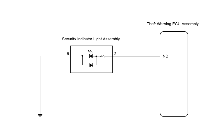
WIRING DIAGRAM
INSPECTION PROCEDURE
PERFORM ACTIVE TEST USING TECHSTREAM (SECURITY INDICATOR LIGHT)
CHECK SECURITY INDICATOR LIGHT ASSEMBLY
CHECK HARNESS AND CONNECTOR (THEFT WARNING ECU - SECURITY INDICATOR LIGHT ASSEMBLY)
CHECK HARNESS AND CONNECTOR (SECURITY INDICATOR LIGHT ASSEMBLY - BODY GROUND)
THEFT DETERRENT SYSTEM (for Sedan) - Security Indicator Light Circuit |
DESCRIPTION
While the theft deterrent system is preparing itself to be set, this circuit lights up the security indicator light. When the system is set, it continuously turns the indicator light on for 0.2 seconds and then turns it off for 1.8 seconds, thus the indicator light blinks.
WIRING DIAGRAM
INSPECTION PROCEDURE
| 1.PERFORM ACTIVE TEST USING TECHSTREAM (SECURITY INDICATOR LIGHT) |
Connect the Techstream to the DLC3.
Turn the ignition switch to ON.
Turn the tester main switch ON.
Select the item below in the Active Test and then check that the security indicator operates.
- Theft Warning ECU:
Item
| Test Details
| Diagnostic Note
|
Security Indicator
| Security indicator light ON/OFF
| -
|
- OK:
- The security indicator light turns on and off correctly when it is operated through the tester.
| OK |
|
|
|
| PROCEED TO NEXT CIRCUIT INSPECTION SHOWN IN PROBLEM SYMPTOMS TABLE |
|
| 2.CHECK SECURITY INDICATOR LIGHT ASSEMBLY |
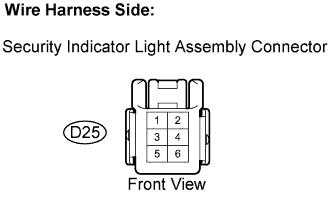
Disconnect the D25 security indicator light connector.
Apply battery voltage to the terminals of the security indicator and check the lighting condition.
- Standard:
Measurement Condition
| Specified Operation
|
Battery positive (+) - Terminal 2
Battery negative (-) - Terminal 6
| Indicator light comes on.
|
Reconnect the indicator light connector.
| 3.CHECK HARNESS AND CONNECTOR (THEFT WARNING ECU - SECURITY INDICATOR LIGHT ASSEMBLY) |
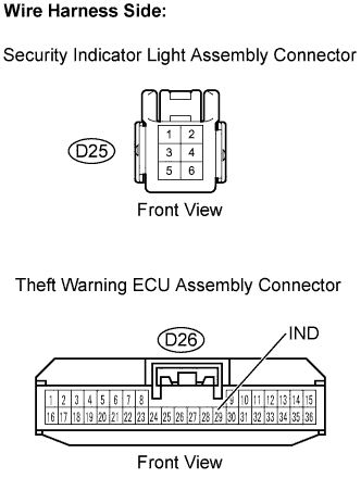
Disconnect the D26 theft warning ECU and the D25 security indicator light connectors.
Measure the resistance.
- Standard resistance:
Tester Connection
| Specified Condition
|
D26-29 (IND) - D25-2
| Below 1 Ω
|
D26-29 (IND) - Body ground
| 10 kΩ or higher
|
Reconnect the theft warning ECU and the security indicator light connectors.
| | REPAIR OR REPLACE HARNESS OR CONNECTOR |
|
|
| 4.CHECK HARNESS AND CONNECTOR (SECURITY INDICATOR LIGHT ASSEMBLY - BODY GROUND) |
Disconnect the D25 security indicator light connector.
Measure the resistance.
- Standard resistance:
Tester Connection
| Specified Condition
|
D25-6 - Body ground
| Below 1 Ω
|
Reconnect the security indicator light connector.
| | REPAIR OR REPLACE HARNESS OR CONNECTOR |
|
|