Theft Deterrent System (For Hatchback) Ecu Power Source Circuit
DESCRIPTION
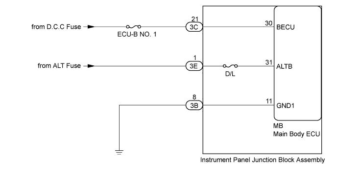
WIRING DIAGRAM
INSPECTION PROCEDURE
CHECK HARNESS AND CONNECTOR (BATTERY - INSTRUMENT PANEL JUNCTION BLOCK ASSEMBLY, BODY GROUND)
CHECK INSTRUMENT PANEL JUNCTION BLOCK ASSEMBLY (POWER SOURCE, BODY GROUND)
THEFT DETERRENT SYSTEM (for Hatchback) - ECU Power Source Circuit |
DESCRIPTION
This circuit provides power for main body ECU operation.
WIRING DIAGRAM
INSPECTION PROCEDURE
- NOTICE:
- Inspect the fuses for circuits related to this system before performing the following inspection procedure.
| 1.CHECK HARNESS AND CONNECTOR (BATTERY - INSTRUMENT PANEL JUNCTION BLOCK ASSEMBLY, BODY GROUND) |
Disconnect the 3C, 3E and 3B instrument panel junction block assembly connectors.
Measure the resistance and voltage according to the value(s) in the table below.
- Standard Resistance:
Tester Connection
| Condition
| Specified Condition
|
3B-8 - Body ground
| Always
| Below 1 Ω
|
- Standard Voltage:
Tester Connection
| Condition
| Specified Condition
|
3C-21 - Body ground
| Always
| 11 to 14 V
|
3E-1 - Body ground
| Always
| 11 to 14 V
|
Text in Illustration*a
| Front view of wire harness connector
(to Instrument Panel Junction Block Assembly)
|
| | REPAIR OR REPLACE HARNESS OR CONNECTOR |
|
|
| 2.CHECK INSTRUMENT PANEL JUNCTION BLOCK ASSEMBLY (POWER SOURCE, BODY GROUND) |
Reconnect the 3B, 3C, and 3E instrument panel junction block assembly connectors.
Remove the main body ECU (YARIS_NCP93 RM000003TOE00CX.html).
Text in Illustration*a
| instrument panel junction block assembly
| -
| -
|
Measure the voltage and resistance according to the value(s) in the table below.
- Standard Voltage:
Tester Connection
| Condition
| Specified Condition
|
MB-30 (BECU) - Body ground
| Always
| 11 to 14 V
|
MB-31 (ALTB) - Body ground
| Always
| 11 to 14 V
|
- Standard Resistance:
Tester Connection
| Condition
| Specified Condition
|
MB-11 (GND1) - Body ground
| Always
| Below 1 Ω
|