Lighting System (For Hatchback) Daytime Running Light Relay Circuit
DESCRIPTION
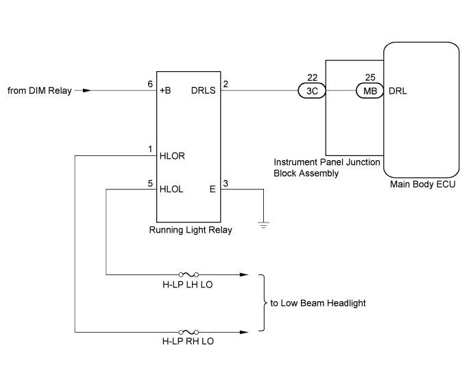
WIRING DIAGRAM
INSPECTION PROCEDURE
PERFORM ACTIVE TEST USING TECHSTREAM
CHECK HEADLIGHT
INSPECT RUNNING LIGHT RELAY
CHECK HARNESS AND CONNECTOR (RUNNING LIGHT RELAY - INSTRUMENT PANEL JUNCTION BLOCK ASSEMBLY)
INSPECT INSTRUMENT PANEL JUNCTION BLOCK ASSEMBLY
LIGHTING SYSTEM (for Hatchback) - Daytime Running Light Relay Circuit |
DESCRIPTION
The main body ECU controls the daytime running lights (dimmed low beam headlights).- HINT:
- The running light relay has a headlight control function. This function dims the low beam headlights in accordance with operation signals from the main body ECU while the daytime running light system is operating.
- The running light relay dims the low beam headlights using a duty control.
WIRING DIAGRAM
INSPECTION PROCEDURE
- NOTICE:
- Inspect the fuses for circuits related to this system before performing the following inspection procedure.
| 1.PERFORM ACTIVE TEST USING TECHSTREAM |
Connect the Techstream to the DLC3.
Turn the ignition switch to ON.
Turn the Techstream on.
Enter the following menus: Body Electrical / Main Body / Active Test.
According to the display on the Techstream, perform the Active Test.
Main BodyTester Display
| Test Part
| Control Range
| Diagnostic Note
|
Daytime Running Light
| Running light relay
| OFF or ON
| -
|
- OK:
- Running light relay operates. (Daytime running lights illuminate.)
Check the operation of the low beam headlights.
- OK:
- Low beam headlights operate normally.
| 3.INSPECT RUNNING LIGHT RELAY |
Remove the running light relay from the No. 2 engine room relay block.
Connect a positive (+) lead from the battery to terminal 6 (+B).
Connect a negative (-) lead from the battery to terminal 2 (DRLS) and 3 (E).
Check for pulses according to the value(s) in the table below.
- OK:
Tester Connection
| Condition
| Specified Condition
|
1 (HLOR) - Battery negative terminal
| Always
| Pulse generation
|
5 (HLOL) - Battery negative terminal
| Always
| Pulse generation
|
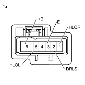
Text in Illustration*a
| Component without harness connected
(Running Light Relay)
|
| 4.CHECK HARNESS AND CONNECTOR (RUNNING LIGHT RELAY - INSTRUMENT PANEL JUNCTION BLOCK ASSEMBLY) |
Remove the running light relay from the No. 2 engine room relay block assembly.
Disconnect the 3C instrument panel junction block assembly connector.
Measure the resistance according to the value(s) in the table below.
- Standard Resistance:
Tester Connection
| Condition
| Specified Condition
|
DRL-2 (DRLS) - 3C-22
| Always
| Below 1 Ω
|
DRL-2 (DRLS) - Body ground
| Always
| 10 kΩ or higher
|
| | REPAIR OR REPLACE HARNESS OR CONNECTOR |
|
|
| 5.INSPECT INSTRUMENT PANEL JUNCTION BLOCK ASSEMBLY |
Remove the instrument panel junction block assembly.
Remove the main body ECU from the instrument panel junction block assembly.
Measure the resistance according to the value(s) in the table below.
Text in Illustration*a
| Component without harness connected
(Instrument Panel Junction Block Assembly)
| -
| -
|
- Standard Resistance:
Tester Connection
| Condition
| Specified Condition
|
3C-22 - MB-25 (DRL)
| Always
| Below 1 Ω
|
| | REPLACE INSTRUMENT PANEL JUNCTION BLOCK ASSEMBLY |
|
|