CHECK DTC (CAN COMMUNICATION SYSTEM)
CHECK CONNECTION OF CONNECTORS
CHECK HARNESS AND CONNECTOR (SOURCE VOLTAGE OF CENTER AIRBAG SENSOR ASSEMBLY)
CHECK HARNESS AND CONNECTOR (SOURCE VOLTAGE OF COMBINATION METER)
AIRBAG SYSTEM (for Sedan) - SRS Warning Light Remains ON |
DESCRIPTION
The SRS warning light is located on the combination meter.When the SRS condition is normal, the SRS warning light illuminates for approximately 6 seconds after the ignition switch is turned from off to on, and then goes off automatically.
If there is a malfunction in the SRS, the SRS warning light illuminates or blinks to inform the driver of the problem. When terminals TC and CG of the DLC3 are connected, the SRS warning light blinks to indicate DTCs.
The center airbag sensor assembly is equipped with a voltage-increase circuit (DC-DC converter) in case the source voltage decreases. When the battery voltage decreases, the voltage-increase circuit (DC-DC converter) boosts the SRS voltage up to the normal level.
Malfunctions relating to battery voltage decreases cause the SRS warning light to illuminate, however, no DTCs are recorded in the center airbag sensor assembly. The SRS warning light goes off automatically when the source voltage returns to normal.
Signals to illuminate the SRS warning light are transmitted from the center airbag sensor assembly to the combination meter through the CAN communication system.
WIRING DIAGRAM

INSPECTION PROCEDURE
- NOTICE:
- In order to prevent unexpected airbag deployment, disconnect the following connectors before inspecting parts such as wire harnesses, if the application of tester probes to the center airbag sensor assembly connector is necessary.
- Turn the ignition switch to the lock position.
- Disconnect the negative (-) terminal cable from the battery, and wait for at least 90 seconds.
- Disconnect the connector from the center airbag sensor assembly.
- Disconnect the connectors from the steering pad.
- Disconnect the connectors from the front passenger airbag assembly.
- Disconnect the connector from the front seat outer belt assembly LH.
- Disconnect the connector from the front seat outer belt assembly RH.
- HINT:
- Skip the following steps if side and curtain shield airbags are not fitted.
- Disconnect the connector from the front seat side airbag assembly LH.
- Disconnect the connector from the front seat side airbag assembly RH.
- Disconnect the connector from the curtain shield airbag assembly LH.
- Disconnect the connector from the curtain shield airbag assembly RH.
| 1.CHECK DTC (CAN COMMUNICATION SYSTEM) |
Turn the ignition switch to the on position.
Check the DTCs (YARIS_NCP93 RM000001D3E00OX.html).
- OK:
- DTC is not output.
|
| ||||
| OK | |
| 2.CHECK BATTERY |
Measure the voltage of the battery.
- Standard voltage:
- 11 to 14 V
|
| ||||
| OK | |
| 3.CHECK CONNECTION OF CONNECTORS |
Turn the ignition switch off.
Disconnect the negative (-) terminal cable from the battery, and wait for at least 90 seconds.
Check that the connectors are properly connected to the center airbag sensor assembly and combination meter.
- OK:
- The connectors are properly connected.
|
| ||||
| OK | |
| 4.CHECK HARNESS AND CONNECTOR (SOURCE VOLTAGE OF CENTER AIRBAG SENSOR ASSEMBLY) |
Disconnect the connectors from the center airbag sensor assembly.
 |
Connect the negative (-) terminal cable to the battery, and wait for at least 2 seconds.
Turn the ignition switch on.
Operate all components of the electrical system (defogger, wipers, headlights, heater blower, etc.).
Measure the voltage.
- Standard voltage:
Tester Connection Switch Condition Specified Condition D16-21 (IG2) -
Body groundIgnition switch ON 11 to 14 V
Turn the ignition switch off.
Measure the resistance.
- Standard resistance:
Tester Connection Condition Specified Condition D16-25 (E1) -
Body groundAlways Below 1 Ω D16-26 (E2) -
Body groundAlways Below 1 Ω
|
| ||||
| OK | |
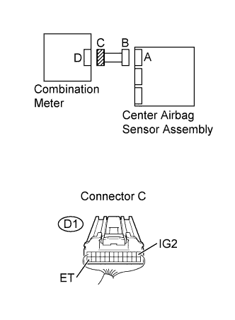
| 5.CHECK HARNESS AND CONNECTOR (SOURCE VOLTAGE OF COMBINATION METER) |
Disconnect the negative (-) terminal cable from the battery, and wait for at least 90 seconds.
 |
Disconnect the connector from the combination meter.
Connect the negative (-) terminal cable to the battery, and wait for at least 2 seconds.
Turn the ignition switch on.
Measure the voltage.- Standard voltage:
Tester Connection Switch Condition Specified Condition D1-1 (IG2) -
Body groundIgnition switch ON 11 to 14 V
Turn the ignition switch off.
Measure the resistance.
- Standard resistance:
Tester Connection Condition Specified Condition D1-24 (ET) -
Body groundAlways Below 1 Ω
|
| ||||
| OK | |
| 6.CHECK SRS WARNING LIGHT |
Turn the ignition switch off.
Disconnect the negative (-) terminal cable from the battery, and wait for at least 90 seconds.
Connect the connector to the combination meter.
Connect the negative (-) terminal cable to the battery, and wait for at least 2 seconds.
Turn the ignition switch on.
Check the SRS warning light condition.
- OK:
- The SRS warning light goes off after the primary check period and comes on again after approximately 10 seconds.
- HINT:
- The primary check period lasts for approximately 6 seconds after the ignition switch is turned on.
|
| ||||
| OK | ||
| ||