REMOVE BRAKE MASTER CYLINDER PUSH ROD CLEVIS (for Manual Transaxle)
REMOVE BRAKE PEDAL SUPPORT SUB-ASSEMBLY (for Manual Transaxle)
REMOVE REAR NO. 2 AIR DUCT (for Cold Area Specification Vehicles)
REMOVE REAR NO. 1 AIR DUCT (for Cold Area Specification Vehicles)
REMOVE REAR NO. 3 AIR DUCT (for Cold Area Specification Vehicles)
Blower Unit (For Sedan) -- Removal |
- CAUTION:
- Some of these service operations affect the SRS airbag system. Read the precautionary notices concerning the SRS airbag system before servicing (YARIS_NCP93 RM000000KT10D1X.html ).
- HINT:
- Use the same procedure for both the RH and LH sides.
| 1. DISCONNECT CABLE FROM NEGATIVE BATTERY TERMINAL |
| 2. DISCHARGE REFRIGERANT FROM REFRIGERATION SYSTEM |
Start up the engine.
Switch A/C ON.
Turn the blower switch to ON.
Operate the cooler compressor with an engine speed of approximately 1,000 rpm for 5 to 6 minutes to circulate the refrigerant and collect the remaining compressor oil from each component, in the cooler compressor.
Stop the engine.
Remove the caps from the service valves on the refrigerant line.
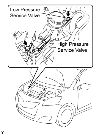 |
Connect the refrigerant recovery unit.
Recover the refrigerant from the air conditioning system using a refrigerant recovery unit.
- NOTICE:
- Use the refrigerant recovery unit in accordance with the manufacturer's instruction manual.
| 3. DRAIN ENGINE COOLANT (for 1NZ-FE) |
- NOTICE:
- To avoid the danger of being burned, do not remove the radiator cap sub-assembly while the engine and radiator assembly are still hot. Thermal expansion will cause hot engine coolant and steam to blow out from the radiator assembly.
Loosen the radiator drain cock plug.
Remove the radiator cap sub-assembly.
Loosen the cylinder block drain cock plug, then drain the coolant.
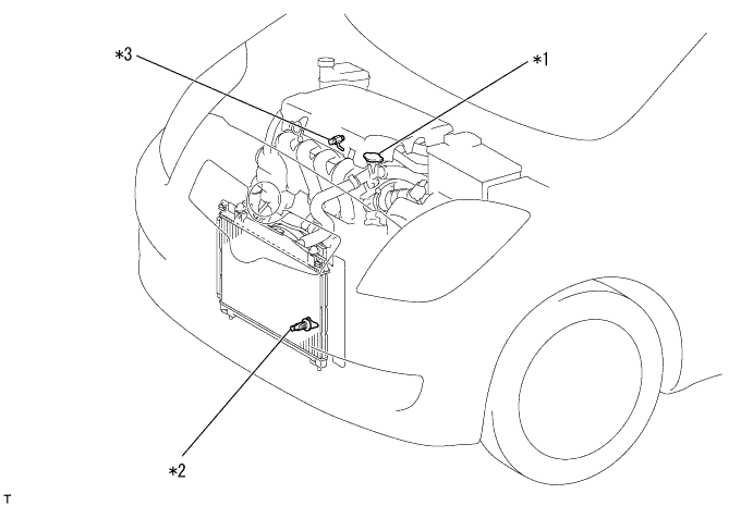
*1 Water Filler Cap Sub-assembly *2 Radiator Drain Cock Plug *3 Cylinder Block Drain Cock Plug - -
| 4. DISCONNECT SUCTION TUBE SUB-ASSEMBLY |
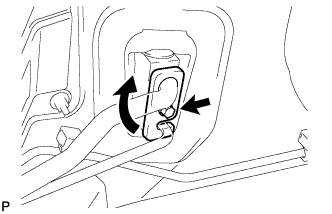 |
Remove the bolt.
Turn the hook type connector clockwise and disconnect the suction tube.
Remove the O-ring from the suction tube.
- NOTICE:
- Seal the openings of the disconnected parts using vinyl tape to prevent moisture and foreign matter from entering.
| 5. DISCONNECT LIQUID TUBE SUB-ASSEMBLY |
Disconnect the liquid tube.
Remove the O-ring from the liquid tube.
- NOTICE:
- Seal the openings of the disconnected parts with vinyl tape to prevent moisture and foreign matter from entering.
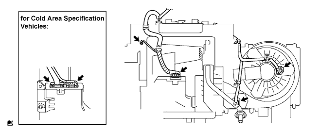
| 6. DISCONNECT HEATER WATER OUTLET HOSE |
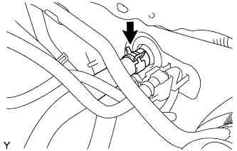 |
Using pliers, grip the claws of the clip, slide the clip and disconnect the heater water outlet hose from the heater unit.
| 7. DISCONNECT HEATER WATER INLET HOSE |
 |
Using pliers, grip the claws of the clip, slide the clip and disconnect the heater water inlet hose from the heater unit.
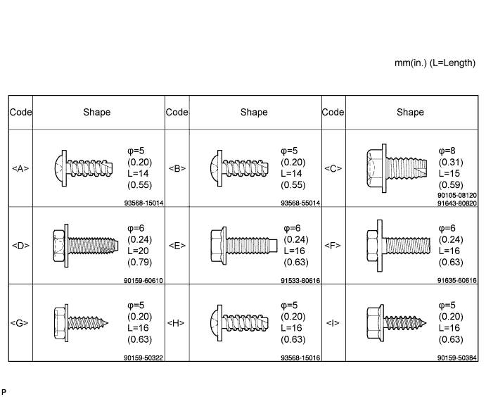
| 8. BOLTS, SCREWS AND NUTS TABLE |
- HINT:
- All bolts, screws and nuts relevant to installing and removing the instrument panel are shown, along with their alphabetic codes, in the table below.
| 9. REMOVE INSTRUMENT PANEL FINISH PANEL LOWER CENTER |
 |
Disengage the 2 claws and 2 clips and remove the instrument panel finish panel lower center.
| 10. REMOVE INSTRUMENT PANEL FINISH PANEL END LH |
 |
Disengage the 6 claws and 3 clips and remove the instrument panel finish panel end LH.
| 11. REMOVE INSTRUMENT PANEL FINISH PANEL END RH |
 |
Disengage the 6 claws and 3 clips and remove the instrument panel finish panel end RH.
| 12. REMOVE INSTRUMENT CLUSTER FINISH PANEL NO.1 |
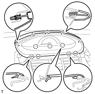 |
Disengage the 7 claws and 5 clips and remove the instrument cluster finish panel.
| 13. REMOVE COMBINATION METER ASSEMBLY |
 |
Disconnect the 2 connectors.
Remove the 2 screws and pull the combination meter rearward to remove it.
| 14. REMOVE INSTRUMENT CLUSTER FINISH PANEL CENTER SUB-ASSEMBLY |
 |
Disengage the 2 claws and 4 clips and remove the instrument cluster panel center.
| 15. REMOVE STEREO OPENING COVER (w/o Radio Receiver) |
 |
Remove the 4 screws and remove the stereo opening cover.
| 16. REMOVE RADIO RECEIVER ASSEMBLY |
for Integrated with Panel:
Disconnect the hazard warning signal switch connector.
Remove the 4 bolts.
Disengage the 4 clips and the 4 claws and remove the radio receiver.
Disconnect the plug.
Disconnect the 3 radio connectors.

 |
except Integrated with Panel:
Remove the 4 bolts and the radio receiver.
Disconnect the plug.
Disconnect the 2 radio connectors.
 |
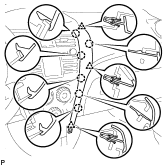
| 17. REMOVE AIR CONDITIONING PANEL ASSEMBLY |
 |
Disengage the 4 clips and 2 claws and remove the air conditioning panel.
Disconnect the 3 connectors and 4 clamps.
 |
| 18. DISCONNECT AIR MIX DAMPER CONTROL CABLE SUB-ASSEMBLY |
 |
Disconnect the air mix damper control cable from the clamp.
Disengage the 2 claws and disconnect the air mix damper control cable.
| 19. DISCONNECT DEFROSTER DAMPER CONTROL CABLE SUB-ASSEMBLY |
 |
Disengage the 2 claws and disconnect the defroster damper control cable.
| 20. DISCONNECT AIR INLET DAMPER CONTROL CABLE SUB-ASSEMBLY |
 |
Disengage the 2 claws and disconnect the air inlet damper control cable.
| 21. SEPARATE FRONT DOOR OPENING TRIM WEATHERSTRIP RH |
| 22. SEPARATE FRONT DOOR OPENING TRIM WEATHERSTRIP LH |
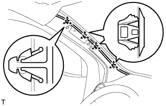
| 23. REMOVE FRONT PILLAR GARNISH RH |
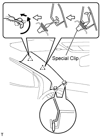
w/ Curtain Shield Airbag:
- NOTICE:
- Install a protective cover onto the curtain shield airbag as soon as the front pillar garnish is removed.
- Replace the special clip with a new one when the front pillar garnish is removed.
Disengage the 2 clips and the 2 claws and remove the front pillar garnish.
 |
w/o Curtain Shield Airbag:
Disengage the 2 clips and the 2 claws and remove the front pillar garnish.
 |
Disconnect the antenna connector.
 |
Using a clip remover, remove the 3 clamps.
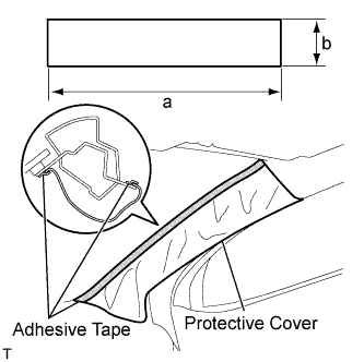
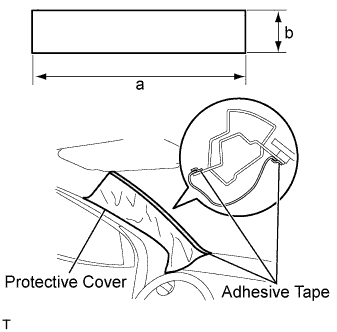
w/ Curtain Shield Airbag:
Completely cover the curtain shield airbag with a piece of cloth or nylon and fix the ends of the fabric with adhesive tape, as shown in the illustration.
- Protective cover size:
Area Measurement a 700 mm (27.56 in.) b 120 mm (4.72 in.)
 |
| 24. REMOVE FRONT PILLAR GARNISH LH |
w/ Curtain Shield Airbag:
- NOTICE:
- Install a protective cover onto the curtain shield airbag as soon as the front pillar garnish is removed.
- Replace the special clip with a new one when the front pillar garnish is removed.
Disengage the 2 clips and the 2 claws and remove the front pillar garnish.
 |
w/o Curtain Shield Airbag:
Disengage the 2 clips and the 2 claws and remove the front pillar garnish.
 |
Using a clip remover, remove the 4 clamps.
 |
w/ Curtain Shield Airbag:
Completely cover the curtain shield airbag with a piece of cloth or nylon and fix the ends of the fabric with adhesive tape, as shown in the illustration.
- Protective cover size:
Area Measurement a 700 mm (27.56 in.) b 120 mm (4.72 in.)
 |
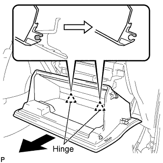
| 25. REMOVE GLOVE COMPARTMENT DOOR ASSEMBLY |
 |
Disengage the claw and separate the 2 glove compartment door stoppers from the glove compartment door.
Slightly flex the upper part of the glove compartment door to release the 2 stoppers and open the glove compartment door assembly until it becomes horizontal.
Pull the glove compartment door assembly out horizontally to disengage the hinge portion and remove the glove compartment door.
- NOTICE:
- Pull the glove compartment door out horizontally, otherwise, installation failure caused by excessive play around the hinge portion will result.
 |
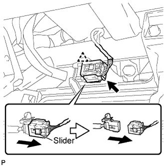
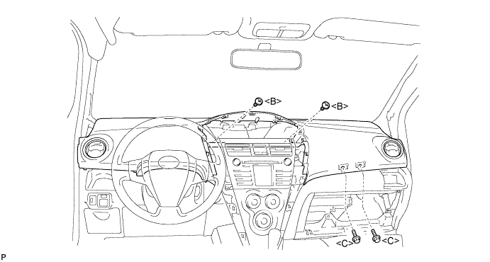
| 26. REMOVE UPPER INSTRUMENT PANEL SUB-ASSEMBLY |
Slide the slider and disconnect the passenger airbag connector.
 |
Disconnect the clamp.
Remove the 2 <C> bolts and 2 <B> screws.
Disengage the 7 clips by lifting the rear side of the instrument panel up.
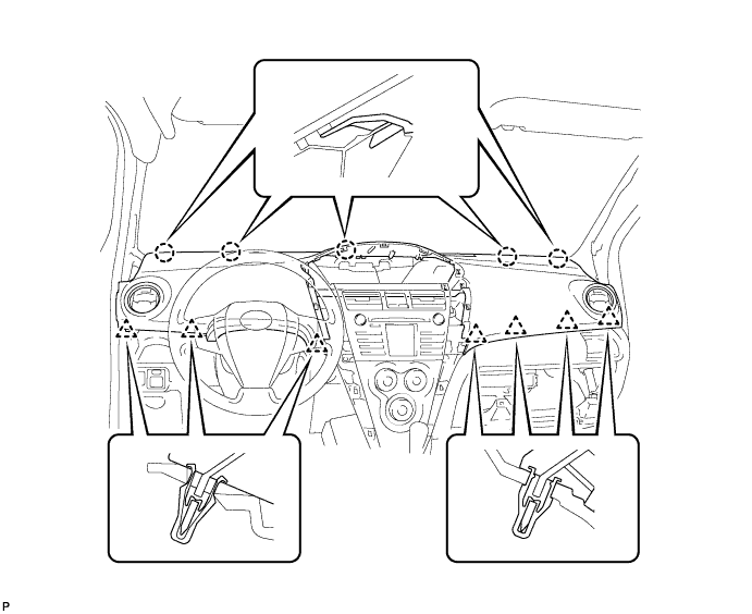
While lifting the instrument panel, slide it toward the rear of the vehicle. Disengage the 5 claws from the front side of the instrument panel and remove the instrument panel.
| 27. REMOVE FRONT DOOR SCUFF PLATE RH |
Disengage the 7 claws and remove the rear door scuff plate.
 |
| 28. REMOVE FRONT DOOR SCUFF PLATE LH |
- HINT:
- Use the same procedure as for the RH side.
| 29. REMOVE INSTRUMENT PANEL UNDER COVER SUB-ASSEMBLY RH |
Disengage the 4 claws and remove the instrument panel under cover.
 |
| 30. REMOVE INSTRUMENT PANEL UNDER COVER SUB-ASSEMBLY LH |
Remove the 2 screws.
 |
Disengage the 3 claws and remove the instrument panel under cover.
| 31. REMOVE COWL SIDE TRIM BOARD RH |
Disengage the claw and the stud bolt and remove the cowl side trim board.
 |
| 32. REMOVE COWL SIDE TRIM BOARD LH |
- HINT:
- Use the same procedure as for the RH side.
| 33. REMOVE SHIFT LEVER KNOB SUB-ASSEMBLY (for Manual Transaxle) |
Remove the shift lever knob.
 |
| 34. REMOVE UPPER CONSOLE PANEL SUB-ASSEMBLY |
Shift the shift lever into the N position.
 |
Disengage the 5 clips and the claw and remove the upper console panel.
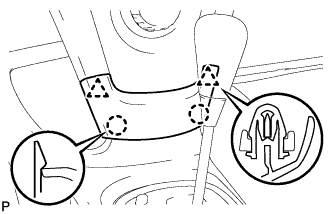
| 35. REMOVE CONSOLE UPPER REAR PANEL SUB-ASSEMBLY |
Disengage the 3 clips and 3 claws.
 |
Disconnect the connector and remove the console upper rear panel.
| 36. REMOVE CONSOLE BOX CARPET |
 |
Remove the console box carpet.
| 37. REMOVE REAR CONSOLE BOX ASSEMBLY |
Disconnect the clamp.
 |
Remove the 2 bolts and 2 screws.
Disengage the 4 claws and remove the rear console box.
| 38. REMOVE INSTRUMENT PAD LOWER LH |
 |
Remove screw <I>.
Disengage the claw and 3 clips and remove the instrument panel pad lower.
| 39. REMOVE INSTRUMENT PAD LOWER RH |
 |
Remove screw <I>.
Disengage the claw and 3 clips and remove the instrument panel pad lower.
| 40. REMOVE INSTRUMENT PANEL LOWER FINISH PANEL SUB-ASSEMBLY |
 |
Disengage the 7 claws and open the instrument panel lower finish panel.
Remove the 2 <A> screws and remove the instrument panel lower finish panel.
 |
| 41. REMOVE INSTRUMENT PANEL BOX |
 |
Open the instrument panel box.
Pull the instrument panel box out horizontally with the instrument panel open and disengage the 2 hinges.
Remove the stopper of the instrument panel box from the cutout of the instrument panel lower and remove the instrument panel box.
 |
| 42. DISCONNECT ANTENNA CORD SUB-ASSEMBLY |
Disconnect the 5 antenna cord clamps.
 |
| 43. SEPARATE HOOD LOCK CONTROL LEVER SUB-ASSEMBLY |
 |
Disengage the 3 claws and separate the hood lock control lever.
| 44. REMOVE LOWER INSTRUMENT PANEL SUB-ASSEMBLY |
 |
Disengage the 2 claws and disconnect the DLC3 connector.
Disconnect the clamps and connectors.
Remove the 6 <D> bolts, 2 <E> bolts, screw <G> and screw <H> and remove the lower instrument panel.

| 45. POSITION FRONT WHEELS FACING STRAIGHT AHEAD |
| 46. REMOVE STEERING PAD |
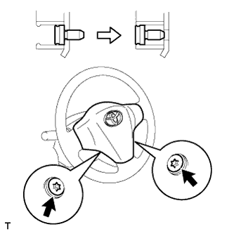 |
Using "Torx" socket wrench T30, loosen the 2 bolts completely.
Pull the steering pad toward you.
Using a thin-bladed screwdriver, release the locking button.
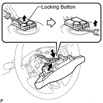 |
Using a thin-bladed screwdriver, disconnect the 2 connectors.
Detach the horn terminal.
| 47. REMOVE STEERING WHEEL ASSEMBLY |
Remove the nut and place matchmarks on the steering wheel assembly and steering column assembly.
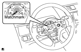 |
Using SST, remove the steering wheel assembly.
- NOTICE:
- Apply a small amount of grease to the threads and tip of the SST center bolt before using.
 |
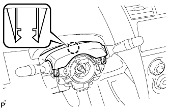
| 48. REMOVE STEERING COLUMN COVER |
Remove the 3 screws, disengage the 2 claws, release the tilt lever and remove the steering column lower cover.
 |
Disengage the claw and remove the steering column upper cover.
 |
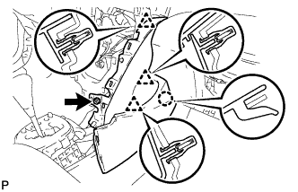
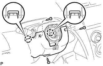
| 49. REMOVE COMBINATION SWITCH ASSEMBLY |
Disconnect all connectors from the turn signal switch with spiral cable.
Disengage the clamp indicated by the arrow in the illustration and remove the combination switch assembly from the steering column assembly.
 |
| 50. DISCONNECT POWER STEERING ECU |
Detach the power steering motor harness and torque sensor wire harness clamps from the power steering ECU side.
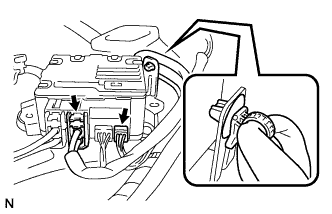 |
Disconnect the 2 steering column assembly connectors from the power steering ECU.
| 51. REMOVE INSTRUMENT PANEL SUB REINFORCEMENT |
Remove the 2 bolts and remove the reinforcement instrument panel sub.
 |
| 52. REMOVE COLUMN HOLE COVER SILENCER SHEET |
Pull back the floor carpet, remove the 2 clips and remove the column hole cover silencer sheet.
 |
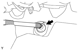
| 53. SEPARATE STEERING SLIDING YOKE SUB-ASSEMBLY |
 |
Place matchmarks on the sliding yoke of the steering intermediate shaft and the power steering link.
Loosen bolt A, remove bolt B and remove the steering yoke.
| 54. REMOVE BRAKE PEDAL (for Automatic Transaxle) |
Using needle-nose pliers, remove the brake pedal return spring.
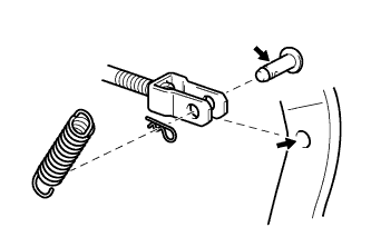 |
Remove the clip from the brake master cylinder push rod clevis pin.
Remove the brake master cylinder push rod clevis pin and detach the push rod clevis from the brake pedal.
Remove the bolt, nut and 2 brake pedal bushes, and remove the brake pedal assembly.
| 55. REMOVE BRAKE MASTER CYLINDER PUSH ROD CLEVIS (for Manual Transaxle) |
 |
Remove the brake pedal return spring.
Remove the clip and the push rod pin and separate the push rod clevis from the brake pedal.
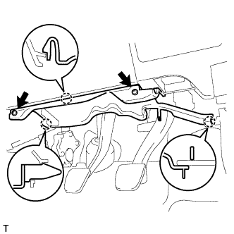
| 56. REMOVE BRAKE PEDAL SUPPORT SUB-ASSEMBLY (for Manual Transaxle) |
 |
Remove the 4 nuts and bolt and remove the pedal support.
| 57. REMOVE STEERING COLUMN ASSEMBLY |
Disconnect all connectors and detach all wire harness clamps from the steering column assembly.
 |
Remove the bolt and 2 nuts and remove the steering column assembly from the instrument panel reinforcement assembly.
| 58. REMOVE HEATER TO REGISTER DUCT ASSEMBLY |
 |
Disengage the 3 claws and remove the heater to register duct.
| 59. REMOVE DEFROSTER NOZZLE ASSEMBLY |
 |
Disconnect the connector and 3 clamps.
Disengage the 5 claws and remove the defroster nozzle.
| 60. REMOVE REAR NO. 2 AIR DUCT (for Cold Area Specification Vehicles) |
 |
Disengage the 4 claws and remove the air duct.
| 61. REMOVE REAR NO. 1 AIR DUCT (for Cold Area Specification Vehicles) |
 |
Disengage the 2 claws and remove the air duct.
| 62. REMOVE REAR NO. 3 AIR DUCT (for Cold Area Specification Vehicles) |
 |
Disengage the 4 claws and remove the air duct.
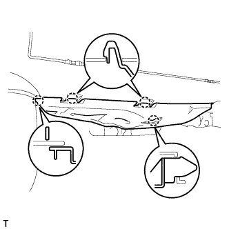
| 63. REMOVE INSTRUMENT PANEL BRACE SUB-ASSEMBLY |
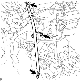 |
Disengage the clamp.
Remove the bolt, screw and nut and remove the instrument panel brace.
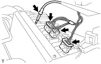
| 64. SEPARATE MAIN BODY ECU (DRIVER SIDE J/B) |
 |
Disconnect the 5 connectors and the 3 clamps.
Remove the 2 bolts and separate the main body ECU.
 |
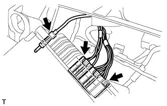
| 65. SEPARATE CONNECTOR NO. 2 HOLDER |
 |
Remove the bolt.
Disconnect the connectors and separate the connector No. 2 holder.
 |
| 66. REMOVE INSTRUMENT PANEL REINFORCEMENT |
 |
Disconnect the drain hose.
Remove the bolt and disconnect the ground wire.
 |
Remove the bolt and disconnect the ground wire. (for Cold area specification vehicles)
 |
Disconnect the connectors.
Disengage the clamps.

Disconnect the connectors and clamps.
Remove the 3 bolts and the nut.

Remove the 9 bolts and remove the instrument panel reinforcement together with the air conditioning unit.

Remove the 3 screws and the air conditioning unit.
 |
| 67. REMOVE BLOWER UNIT |
 |
Remove the 3 screws and the blower unit.